MV_SPLIT (Split Range Controller) Logic Block Documentation
Overview
The MV_SPLIT block is an essential control module in process automation systems designed to implement split-range control. It allows a single manipulated variable (MV)—typically from a PID or control logic—to be distributed across two separate actuators (e.g., control valves or dampers) based on predefined ranges.
This logic is commonly used in: - Temperature control (heating/cooling valves) - Flow control (dual parallel valves) - Pressure control systems
By managing how each actuator responds to different ranges of the MV, the block ensures: - Smooth transitions - Optimized actuator usage - Improved loop stability
Logic Block Illustration
The MV_SPLIT logic block is used to control and monitor a split-range control valve, typically used in analog control loops. It divides the input signal to operate two actuators or two ranges of a single actuator, allowing fine-grained control over a wider operational range.
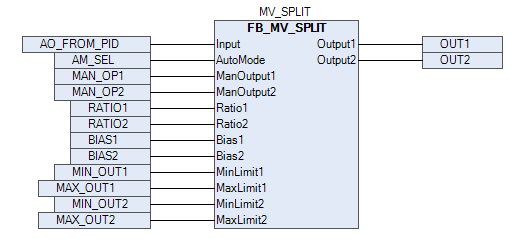
A visual representation of the MV_SPLIT block, showing its function in distributing a single control signal into two separate actuator signals, depending on the configured range.
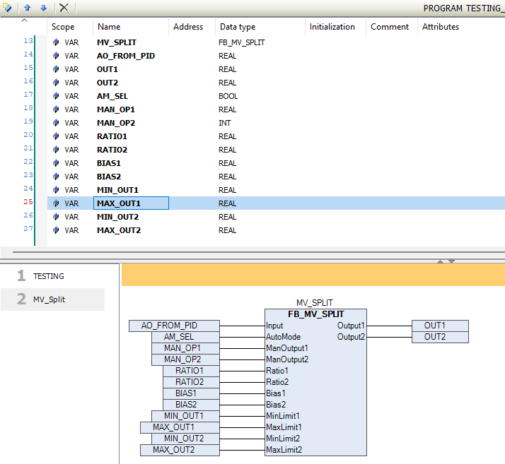
The above pictures show how the inputs and outputs are connected in the MV_SPLIT block.
This illustration shows the correct signal mapping and usage of the MV_SPLIT block within a process automation program, including control signal ranges and output behavior for dual-valve control.
Functional Description
- In Auto Mode, the block uses the
InputMV signal and calculates the outputs based on: - Defined limits (
MinLimit1,MaxLimit1, etc.) -
Ratios and biases (
Ratio1,Bias1, etc.) -
In Manual Mode, users can directly set outputs using:
ManOutput1andManOutput2
This allows for both automated split control and manual override during commissioning or testing.
Input and Output Parameters
| Signal | Type | Description |
|---|---|---|
Input |
REAL |
Main manipulated variable (MV) typically from PID |
AutoMode |
BOOL |
Mode selection: TRUE = Auto, FALSE = Manual |
ManOutput1 |
REAL |
Manual override value for Output1 |
ManOutput2 |
REAL |
Manual override value for Output2 |
Ratio1 |
REAL |
Scaling ratio for Output1 |
Ratio2 |
REAL |
Scaling ratio for Output2 |
Bias1 |
REAL |
Bias (offset) for Output1 |
Bias2 |
REAL |
Bias (offset) for Output2 |
MinLimit1 |
REAL |
Minimum clamp for Output1 |
MaxLimit1 |
REAL |
Maximum clamp for Output1 |
MinLimit2 |
REAL |
Minimum clamp for Output2 |
MaxLimit2 |
REAL |
Maximum clamp for Output2 |
Output1 |
REAL |
Final calculated Output1 value |
Output2 |
REAL |
Final calculated Output2 value |
Operational Logic
🔄 Auto Mode (AutoMode = TRUE)
- Output values are automatically calculated based on the live
Input, adjusted byRatioandBias, and bounded within definedMinandMaxlimits.
🔧 Manual Mode (AutoMode = FALSE)
- Allows the operator to directly assign values to
ManOutput1andManOutput2. - Useful in the following cases:
- 🔧 Plant commissioning and tuning
- 🚨 Manual override during fault or abnormal conditions
- 🔄 Temporary bypass of automation logic
- Outputs are still clamped between the configured limits to ensure safety and consistency.
Training Demo Video
Demonstration video is available , How to use the MOV_INCHING Logic Block through Library:
MV-Split Block Demo - TPW Logic Setup
Use Case Scenario
💡 Example 1: Valve Split Control
- Valve 1: operates from 0%–50% MV
- Valve 2: operates from 50%–100% MV
```text
Ratio1 = 1.0, Bias1 = 0, MinLimit1 = 0, MaxLimit1 = 50
Ratio2 = 1.0, Bias2 = -50, MinLimit2 = 0, MaxLimit2 = 50