Installation of FTA (Field Terminal Assembly)
Introduction
The Field Terminal Assembly (FTA) acts as a bridge between your PLC system and field devices like sensors and actuators. It ensures that wiring is organized, safe, and easy to maintain. In this section, you’ll learn about the types of FTAs, how they function, and how to properly install them in your control panel.
This guide will walk you through:
- Types of FTAs (Active & Passive)
- Benefits of using FTAs
- Step-by-step installation procedure
What is FTA?
FTA (Field Terminal Assembly) is a modular interface that connects your field wiring to the PLC modules. It helps keep wiring:
- Neat
- Safe
- Easy to manage and maintain
How Does FTA Work?
- Connects field devices (like sensors, valves) directly to the PLC
- Keeps wiring organized and accessible
- Comes in two types:
- Active FTA (with built-in electronics)
- Passive FTA (basic connector-only interface)
Types of FTA
1️⃣ Active FTA
- Includes internal electronics
- Supports diagnostics (troubleshoot without disconnecting wires)
- Works with:
- Analog Output (AO) modules
- Digital Input (DI) modules
- Requires a 24V DC power supply
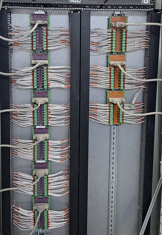
Color Coding for Quick Identification: - AO → Orange - DI → Green
2️⃣ Passive FTA
- Basic interface without electronics
- Uses screw terminals and Prefabricated DB-37 cable
- Color: Green
- No external power required
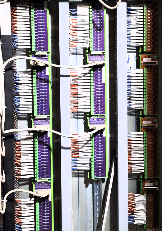
Color Coding for Quick Identification: - AI → Magenta - DO → Green
Why Use an FTA?
- Keeps your wiring clean and professional
- Minimizes installation errors
- Speeds up troubleshooting and maintenance
- Protects both the PLC and field devices
Installation Process for FTA
Follow these steps to install your FTA safely and efficiently:
Step 1: Mount the FTA
- Mount the FTA onto the DIN rail inside the panel
- Ensure it clicks and locks into place
- Can be mounted in either horizontal or vertical orientation
Step 2: Connect the FTA to the PLC Module
- Use a Prefabricated DB-37 cable to connect the FTA (Field Terminal Assembly) to the PLC module.
- Plug the Prefabricated DB-37 cable into the matching port on the PLC module.
- Make sure the connection is firm and properly locked to avoid signal issues.
Step 3: Wire the Field Devices
- Connect sensors or actuators to the screw terminals on the FTA
- Refer to the wiring diagram and terminal labels
- Strip wires to about 7 mm and use ferrules for clean connections
Step 4: Tighten the Terminal Screws
- Use a screwdriver to tighten each terminal to 0.5–0.6 Nm
- Ensure proper contact, but do not overtighten
Step 5: Power Up (For Active FTA Only)
- Connect the 24V DC power supply to the Active FTA.
- Check that the Power LEDs on both the FTA and the PLC are glowing, confirming that power is properly supplied.
Step 6: Verify Connections and Status
- Observe status LEDs on the FTA and PLC
- If all are ON, connections are correct
- If any LED is OFF or blinking, recheck your wiring
💡Tips for Better Installation
- Label all cables for easy identification
- Keep wiring organized with cable ties
- Use standard color codes wherever possible
- Always refer to the FTA datasheet for specific pinout and specs