VFD MON Documentation
This is Varible Frequency Drive which is used for the monitoring the RPM and Ampere of the motor.
Block Icon
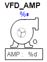
This VFD block icon have two parts first is motor and another is PID to show the ampere.
Motor :
When we click on the motor then motor faceplate open where we can see the details related to the motor.
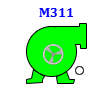
The motor block icon provides a visual representation of the motor’s state using color-coded indicators. Each color or blinking combination signifies a specificoperating condition, helping operators quickly identify the motor's current status.
- 1 Tag Number: Displays the process tag.
- 2 Motor body: Displays information regarding the motor’s status and operation.
- 3 Moving Ring : Displays the direction of the motor(reverse or forward).
i. Red : Motor is ready to run.

ii. Green : Motor is running.
iii. Blinking Magenta and Red : Motor is Tripped.

iv. Blinking Yellow and Red : Permission not satisfied in Motor .

v. Blinking Blue and Red : Interlock occured in Motor .

vi. Green with yellow circle : Motor running with permission bypassed .

vii. Green with yellow Blue : Motor running with interlock bypassed .

Motor Faceplate
In the Motor REV faceplate, there are 4 tabs:
-
Operation Tab : For the operation of the motor.
-
Basic Tab : Displays basic feedback and operational summary.
-
Advance Tab : Advanced options for motor configuration and setup.
-
Diagnostics Tab : Shows all feedback and diagnostic parameters.
Operator Tab Description
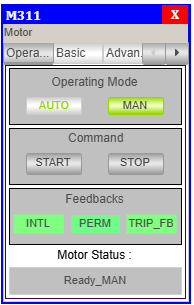
Operating Mode:
- AUTO – Enables automatic mode (commands from logic or PLC).
- MAN – Enables manual mode (commands via HMI).
- The currently selected mode is highlighted in green.
Control Command:
- START FWD(forward) – Sends command to start the motor in Clockwise direction which can be seen in block icon.
- START REV(reverse) – Sends command to start the motor in anticlockwsie direction which can be seen in block icon.
- STOP – Sends command to stop the motor.
- These buttons are only active in manual mode.
Feedbacks:
| Feedback | Description | Status Indicator |
|---|---|---|
| INTL | Interlock conditions are valid | 🟢 = OK 🟡 = Interlock Occurred |
| PERM FWD | Start motor in clockwise permission | 🟢 = OK 🟡 = Permission Not Satisfied |
| PERM REV | Start motor in anticlock permission | 🟢 = OK 🟡 = Permission Not Satisfied |
| Trip Feedback | Indicates motor fault or trip condition. | =TRIP OK = TRIP |
Motor Status:
- This field displays the current state of the motor.
- Status example in image:
Ready_MAN
> Meaning: Motor is ready and in manual mode.
Basic Tab Description
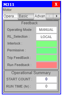
Feedbacks:
| Label | Description | Example Shown |
|---|---|---|
| Operating Mode | Displays the current control mode of the motor. | MANUAL OR AUTO |
| RL_Selection | Shows the remote/local control selection. | LOCAL OR REMOTE |
| Interlock | Indicates whether all interlocks are satisfied. | 🟢 = OK 🟡 = Interlock Occurred |
| Permissive FWD | Shows if permissive conditions are met for motor start in clockwise direction. | 🟢 = OK 🟡 = Permission Not Satisfied |
| Permissive REV | Shows if permissive conditions are met for motor start in anticlockwise direction. | 🟢 = OK 🟡 = Permission Not Satisfied |
| Trip Feedback | Indicates motor fault or trip condition. | = TRIP OK = TRIP |
| Run FB FWD | Shows whether the motor is currently running in clockwise direction. | 🟢 = Running 🔴 = Not Running |
| Run FB REV | Shows whether the motor is currently running in anticlockwise direction. | 🟢 = Running 🔴 = Not Running |
Operational Summary:
- RUN TIME – Total Motor Run time.
Advance Tab Description
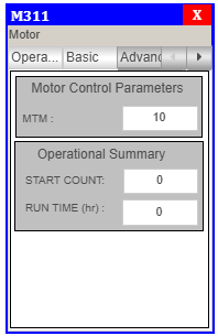
Motor Contol Parameter:
- MTM - This is the time(sec) upto which motor wait for the run feedback otherwise goes in fault.
Operational Summary:
- RUN TIME – Total Motor Run time.
Motor REV Diagnotics Tab
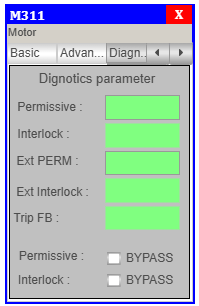
Diagnotics parameter
- Permissive FWD –
greencolor when permission FWD is OK andyellowcolor when permission FWD not satisfy. - Permissive REV –
greencolor when permission REV is OK andyellowcolor when permission REV not satisfy. - Interlock –
greencolor when Interlock is OK andyellowcolor when Interlock occurs. - Trip –
greencolor when Trip is OK andmagentacolor when Trip occurs. - Perm FWD – click on checkbox to
bypassthe permission for clockwise direction. - Perm REV – click on checkbox to
bypassthe permission for anticlockwise direction. - Interlock – click on checkbox to
bypassthe interlock.
AMP:
It shows the ampere of the motor. - when we click on the AMP button it opens a PID facepalte using which we can increase and decrease Ampere of the motor.
Faceplate Tabs
Basic Level Tab
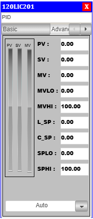
PID Basic Faceplate Description
- PV (Process Variable): Real-time value from sensor.
- SV (Setpoint Variable): Target value set for process control.
- MV (Manipulated Variable): PID controller output.
- MVLO (Min MV): Minimum value allowed for manipulated output.
- MVHI (Max MV): Maximum value allowed for manipulated output.
- L_SP (Local Setpoint): Local setpoint value(given by Operator)
- C_SP (Cascade Setpoint): Cascade setpoint reference.(Calculated setpoint)
- SPLO: Lower override limit for setpoint.
- SPHI: Upper override limit for setpoint.
Advanced Level Tab
On clicking the Adva button, the Adva Tab will open.
Only authorized users can access this after logging in.
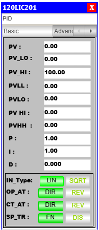
PID Advanced Faceplate Description
Control Mode & Action Selection
- Output Action (OP_AT): Sets the controller output to Direct (DIR) or Reverse (REV).
- Control Action (CT_AT): Defines the internal control mode as Direct (DIR) or Reverse (REV).
- Setpoint Tracking (SP_TR): Enables (EN) or disables (DIS) setpoint tracking.
Alarm & Process Variables
- PV: Real-time process variable value.
- PV_LO: Low limit for process variable.
- PV_HI: High limit for process variable.
- PVLL: Very low alarm threshold.
- PVL0: Low alarm threshold.
- PVHI: High alarm threshold.
- PVHH: Very high alarm threshold.
PID Tuning Parameters
- P (Proportional Gain): Controls response to present error.
- I (Integral Time): Eliminates accumulated error over time.
- D (Derivative Time): Predicts future error based on rate of change.
Process Variable Limits
- PVHH: Critical upper process variable limit.
- PVHI: Warning-level high limit.
- PVLO: Warning-level low limit.
- PVLL: Critical lower process variable limit.
Faceplate Interface & Navigation
- Tag Number: Shows PID block tag (e.g.,
120HBP101). - Toggle Switches & Action Buttons: Used for mode switching.
- Tuning Adjustment Section: Area for modifying P, I, D values.
- Action Mode Indicators (Green Highlight): Indicates currently active state.
Alarm Handling Logic
The PID block includes robust alarm handling features for process safety and operator awareness. The alarm window behavior is as follows:
Low Alarm
- When a Low Alarm occurs:
- The alarm window starts blinking to indicate an active alarm.
- When the Acknowledge (ACK) button is pressed:
- The alarm is acknowledged.
- The blinking stops.
Very Low Alarm
- When a Very Low Alarm occurs:
- The alarm window starts blinking to indicate an active alarm.
- When the ACK button is pressed:
- The alarm is acknowledged.
- The blinking stops.
High Alarm
- When a High Alarm occurs:
- The alarm window starts blinking to indicate an active alarm.
- When the ACK button is pressed:
- The alarm is acknowledged.
- The blinking stops.
Very High Alarm
- When a Very High Alarm occurs:
- The alarm window starts blinking to indicate an active alarm.
- When the ACK button is pressed:
- The alarm is acknowledged.
- The blinking stops.
The ACK button is essential for managing active alarms and restoring a clear view on the HMI after operator intervention.