Visualization Documentation – MANUAL LOADER (MLD) Block
Usage of MLD Block through SCADA Template
The MLD (Manual Loader) block provides manual override control for analog output values.
It is commonly used during calibration, troubleshooting like situations to override automatic control signals with manually defined safe values.
This block is designed as a reusable faceplate visualization component, integrated using SCADA template-based design.
The graphical icon is pre-configured and reused from the Visu_page.
Integrating the MLD Block into Visualization
1. Open Your Visualization Page
- Open your CODESYS project.
- Navigate to the required HMI screen (e.g.,
Analog_Override,Process_Control).
2. Insert the MLD Block Icon from Scada_test visu page
- Open the Visualization Toolbox Go to Current Project.
- Drag or drop the MLD block icon to your Visualization page.
- Or Just Copy the MLD Block Icon from the
Scada_testvisu page and Paste into your Visualization page.
✅ Enables reuse of a standardized, tested faceplate block across screens.
3. Link the MLD Block to Its Logic Instance
- Select the MLD block icon.
- click on the block icon Properties tab open automatically → Properties.
- Go to the References and Expand the references.
- you will see bl_MLD Expand that also.
- set the path in front of the tagManual_loader_fp by Double clicking on empty space and select the required tag.
- Build and run the project.
- During runtime, click on the MLD icon to open its faceplate and confirm real-time control.
MLD Block Icon – Visualization Behavior

| No. | Visual Element | Description |
|---|---|---|
| 1 | Tag Label | Click to open the faceplate. |
| 2 | Mode Indicator (A/M) | Shows current mode: Auto or Manual. |
| 3 | Output Display | Displays real-time output value. |
MLD Faceplate Overview
Clicking the MLD icon opens a faceplate with parameters to toggle between Auto and Manual mode, and configure manual output.
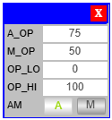
Faceplate Parameters
| Field | Description |
|---|---|
A_OP |
Auto value. Used as output in Auto mode. |
M_OP |
Manual override value. Used in Manual mode. |
OP_LO |
Lower limit for manual value. |
OP_HI |
Upper limit for manual value. |
AM |
Mode selection: Auto (A) or Manual (M). |
Operating Modes
Auto Mode
- Default mode of operation.
- Output follows the value of
A_OP(auto input). - Suitable for steady-state or normal process operation.
Manual Mode
- Output is set to user-defined
M_OP. - Useful for testing, sensor failure, or maintenance.
- Manual value is clamped within
OP_LOandOP_HI.
Safety via Output Limits
| Parameter | Function |
|---|---|
OP_LO |
Prevents output from falling below a safe minimum. |
OP_HI |
Prevents output from exceeding a safe maximum. |
- Limits are enforced even during manual override to protect field equipment.
Operator Access Levels
| Role | Access Level |
|---|---|
| Operator | May view and switch modes, if permitted. |
| Engineer | Can set M_OP, OP_LO, and OP_HI. |
| Admin | Full access including disabling faceplate if needed. |
Integration Tips
- Always assign the correct Element Variable.
- Use SCADA alarms in parallel for improper override detection.
- Validate limits (
OP_LO,OP_HI) against your system’s physical capabilities. - Prevent excessive toggling between Auto and Manual during live operation.
Summary
The MLD block enables reliable analog signal override control with boundary protection.
It is essential for safe operations during signal failure, commissioning, or maintenance tasks.
✅ Supports Auto and Manual modes
✅ Safe manual override with upper/lower output limits
✅ Clean faceplate with operator-friendly interface
✅ Reusable icon with drag-and-drop integration
✅ Access-controlled for operator and engineer roles
Ideal for analog actuator overrides and controlled intervention in process loops.