PID_ET Controller Logic Documentation
Overview
A PID_ET (Proportional–Integral–Derivative with External Tuning) controller is a time-dependent PID control mechanism that allows external control of the execution interval. This is especially useful in applications with non-periodic execution, or when the control interval needs to be synchronized with external events or slower tasks.
This controller reduces human intervention and ensures consistent automatic process regulation using feedback.
Like standard PID, it minimizes the error (e(t)) between the Setpoint (SP) and Process Variable (PV) using:
- Proportional (P): Correction based on current error.
- Integral (I): Correction based on accumulated past error.
- Derivative (D): Correction based on prediction of future error trends.
The
PID_ETcontroller increases timing accuracy in advanced process systems with variable cycles or event-driven calls.
Logic Block Illustration
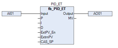
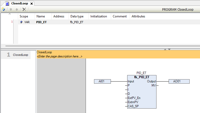
In above picture, we are showing inputs and output of PID-ET block.
PID_ET Function Block – Pins Information
| Signal | Type | Description |
|---|---|---|
INPUT |
WORD |
Raw analog signal input from the field. |
PV_LO |
REAL |
Minimum range value for scaling the process variable (PV). |
PV_HI |
REAL |
Maximum range value for scaling the process variable (PV). |
LOC_SP |
REAL |
Local setpoint (operator-entered value). |
REM_SP |
REAL |
Remote setpoint from another logic block/system. |
CAS_SP |
REAL |
Cascade setpoint used in cascade control mode. |
SP_LO_LM |
REAL |
Setpoint low limit. |
SP_HI_LM |
REAL |
Setpoint high limit. |
MVLO |
REAL |
Lower limit of PID output (MV). |
MVHI |
REAL |
Upper limit of PID output (MV). |
P |
REAL |
Proportional gain. |
I |
REAL |
Integral time constant. |
D |
REAL |
Derivative time constant. |
MODE |
BYTE |
Controller mode: 0 = Manual, 1 = Auto, 2 = Cascade, 3 = Remote. |
CTRL_ACTN |
BIT |
TRUE = Direct acting; FALSE = Reverse acting. |
DIR |
BIT |
FALSE = Direct output; TRUE = Reverse output. |
SP_TRACK |
BIT |
If TRUE, SV tracks PV (e.g., during mode change). |
ExtPV_En |
BIT |
If TRUE, ExtrnPV overrides internal PV. |
ExtrnPV |
REAL |
External PV value (if enabled). |
FILTER |
REAL |
Filtering coefficient for noise reduction on PV. |
PVLL |
REAL |
Very low alarm limit for PV. |
PVLO |
REAL |
Low alarm limit for PV. |
PVHI |
REAL |
High alarm limit for PV. |
PVHH |
REAL |
Very high alarm limit for PV. |
OPLL |
REAL |
Very low alarm limit for Output (MV). |
OPLO |
REAL |
Low alarm limit for Output (MV). |
OPHI |
REAL |
High alarm limit for Output (MV). |
OPHH |
REAL |
Very high alarm limit for Output (MV). |
HYST |
REAL |
Hysteresis value for PV and Output alarms. |
ACK |
BIT |
Acknowledgement input for alarms. |
RTN_ACK_REQD |
BIT |
If TRUE, return-to-normal alarms require acknowledgment. |
IN_LO |
REAL |
Output signal low limit from the program. |
IN_HI |
REAL |
Output signal high limit from the program. |
OP_LO |
WORD |
Raw AO output - minimum raw value. |
OP_HI |
WORD |
Raw AO output - maximum raw value. |
PID_OP |
REAL |
Manual value applied when in manual mode. |
PV |
REAL |
Scaled process variable derived from input. |
SV |
REAL |
Selected setpoint (LOC_SP / REM_SP / CAS_SP). |
MV |
REAL |
Calculated output from PID (0–100%). |
Output |
WORD |
Final raw analog output to AO channel. |
PV_LL_ALM |
BIT |
TRUE when PV < PVLL. |
PV_LO_ALM |
BIT |
TRUE when PV < PVLO. |
PV_HI_ALM |
BIT |
TRUE when PV > PVHI. |
PV_HH_ALM |
BIT |
TRUE when PV > PVHH. |
OP_LL_ALM |
BIT |
TRUE when Output < OPLL. |
OP_LO_ALM |
BIT |
TRUE when Output < OPLO. |
OP_HI_ALM |
BIT |
TRUE when Output > OPHI. |
OP_HH_ALM |
BIT |
TRUE when Output > OPHH. |
WireBreak |
BIT |
TRUE indicates analog input wire break. |
WireShort |
BIT |
TRUE indicates analog input wire short. |
Acknowleged |
BIT |
TRUE if alarms are acknowledged; resets when ACK is triggered. |
TagName |
STRING(10) |
Tag identifier for this PID_ET instance. |
Desc |
STRING(12) |
Description of the function block for SCADA/HMI reference. |
Important Notes
- External Timing (
dt) must be provided every execution cycle. - Manual Mode overrides controller output with
MV_MAN. - Reset Input (
RESET) clears integrator and derivative memory. - BIAS allows feedforward output correction for improved response.
- All alarm outputs depend on PV limit values and hysteresis.
Alarm Handling:
Each alarm bit output (PV_LL_ALM,PV_LO_ALM, etc.) is activated based on defined PV limits. Alarms can be acknowledged using theACKinput.
Typical PID_ET Workflow
- PV is read from sensor (optionally filtered).
- Controller compares SP with PV.
- Calculates ERROR = SP - PV.
- Applies P, I, D control using externally provided
dt. - Adds
BIASto generate totalMV. - Applies clamping to enforce
MV_MINandMV_MAX. - Output
MVis used to control actuator. - In manual mode,
MV=MV_MAN.
Faceplate Display Recommendations
- Display SP, PV, and MV in real time.
- Show current control mode (Auto/Manual).
- Allow operator to enter
MV_MANand acknowledge alarms. - Display alarm statuses and limits on faceplate.
Use Cases
- Temperature control with variable scan times.
- Valve positioning in event-driven control loops.
- Level control in asynchronously updated systems.
- Remote PID tuning where you cannot guarantee task timing.
Tip:
Use high-resolution timers or synchronize with a process scheduler to ensure consistentdt. Poorly timed or fluctuatingdtvalues will cause erratic control.