Visualization Documentation - PIDDT Block
Usage of PID_DT Block in Visualization
PID_DT, which stands for PID dual tuning, is a critical methodology employed in various industrial processes. It is particularly advantageous in scenarios where liquid extraction from a tank must occur against back pressure or when liquid is being pumped from the same tank, thereby underscoring the significance of PID_DT in optimizing control systems in these contexts.
Integrating the PID_DT Block into Visualization steps are given below:
1. Open the Visualization Page
- Open your CODESYS project.
- Navigate to your visualization page (e.g.,
PID_DT Control) where the PID icon will be reused.
2. Insert the PID_DT Block Icon from Scada_test Visu Page
- Open the Visualization Toolbox Go to Current Project.
- Drag or drop the PID_DT Block icon to your Visualization page.
- Or Just Copy the PID_DT Block Icon from the
Scada_testvisu page and Paste into your Visualization page.
3. Set Referencing Properties
Once the PID_DT block icon is placed on your custom page, link it to the logic block by following these steps:
- Select the PID_DT block icon.
- click on the block icon Properties tab open automatically → Properties.
- Go to the References and Expand the references.
- you will see bl_PID_DT Expand that also.
- set the path in front of the tagPID by Double clicking on empty space and select the required tag.
- Build and run the project.
- During runtime, verify that live values like
PV,SVandMVfunctioning.
PID_DT Block Icon – Visualization Behavior
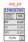
Clicking on the Tagname of the PID block icon opens its faceplate, allowing for real-time operation and tuning.
PID_DT Faceplate Overview
The faceplate is divided into two main tabs for different user levels:
- Basic Tab
- Advanced Tab
Basic Tab
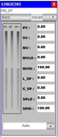
Provides a quick overview of key process parameters and allows mode selection.
This tab is visible to all users, including operators.
PID_DT Parameter Details: Basic Tab
| Section | Parameter | Description |
|---|---|---|
| Process Values | PV |
Real-time process variable value from the sensor. |
SV |
Setpoint value defining the target for control. | |
MV |
Manipulated variable – controller output signal to actuator. | |
| Output Limits | MVLO |
Minimum limit for the manipulated value (MV). |
MVHI |
Maximum limit for the manipulated value (MV). | |
| Setpoint Settings | L_SP |
Lower engineering limit for setpoint adjustment. |
C_SP |
Central (default) setpoint reference used in auto/manual transitions. | |
SPLO |
Runtime low override limit for setpoint value. | |
SPHI |
Runtime high override limit for setpoint value. | |
| PV Bar | PV |
On the left side there is PV bar which show the PV value in visual form. |
| SV Bar | SV |
On the left side there is PV bar which show the SV value in visual form. |
| MV Bar | MV |
On the left side there is PV bar which show the MV value in visual form. |
| Mode Selector | Mode |
Select the mode of the PID By clicking on the dropdown arrow. |
Advanced Tab
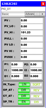
Used for advanced tuning and alarm settings. This tab is typically restricted to Operators.
PID_DT Parameter Details: Advanced Tab
| Section | Parameter | Description |
|---|---|---|
| Process Variables (PVs) | PV |
Real-time process variable input. |
| Process Value Limit | PV_LO |
Low alarm limit for process variable. |
PV_HI |
High alarm limit for process variable. | |
| Alarming Limits | PVLL |
Critical low alarm (very low limit). |
PVLO |
Warning-level low limit. | |
PV HI |
Warning-level high limit. | |
PVHH |
Critical high alarm (very high limit). | |
| PID Tuning | P1 and P2 |
Proportional Gain – P1 and P2. |
I1 and I2 |
Integral Time – I1 and I2. | |
D1 and D2 |
Derivative Time – D1 and D2. | |
| Control Type | IN_Type |
Input type for PID: Linear (LIN) or Square Root (SQRT). |
| Controller Behavior | OP_AT |
Output Action – Direct (DIR) or Reverse (REV) controller response. |
CT_AT |
Control Action – Internal logic set to Direct (DIR) or Reverse (REV). |
|
| Setpoint Tracking | SP_TR |
Enables (EN) or disables (DIS) tracking setpoint during mode change. |
Used for tuning the controller behavior, and adjust these values carefully based on process tuning recommendations.
Notes
- Ensure the
PIDfunction block is correctly declared in your logic before referencing in visualization.- Use user access control if tuning parameters should be restricted by role. As it is not accessible by Operator.
- You can also set visibility conditions or animations to dynamically show PID status.
Training or Demo Video
Demonstration video is available, embed in the link below:
Summary
The PID_DT block in the TPW HMI enables intuitive real-time monitoring and control of closed-loop systems.
Using its configurable faceplate, users can visualize process variables, manipulate control values, and perform advanced tuning all from within the HMI environment.
This makes the PID block ideal for both operators and engineers looking for a seamless process control interface.