PID-MR Controller Logic Documentation
Overview
The Manual Reset feature in the PID-MR block allows operators to intervene and override the PID output when necessary. This is particularly useful during startup, maintenance, or abnormal operating conditions.
When Manual Reset is active:
- The External MV (Manipulated Variable) input becomes active.
- The controller bypasses PID computation and directly outputs the value provided by the
EXT_MVinput. - The operator can manually control the process output until automatic control is restored.
Logic Block Illustration
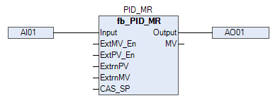
In above picture, we are showing inputs and output of PID-MRET block.
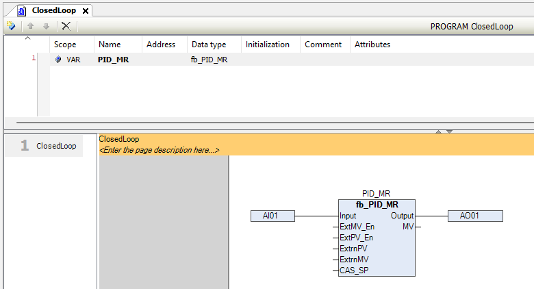
In the above picture, we are showing that how to use the PID-MR block.
PID_MR Block – Pins Information
| Signal | Type | Description |
|---|---|---|
INPUT |
WORD | Raw input from analog channel |
PV_LO |
REAL | PV low scaling range |
PV_HI |
REAL | PV high scaling range |
RTN_ACK_REQD |
BIT | Return-to-Normal condition requires acknowledgment |
ACK |
BIT | Alarm acknowledgment input |
Acknowledged |
BIT | Alarm acknowledgment status output |
WireBreak |
BIT | Output TRUE when wire break detected |
WireShort |
BIT | Output TRUE when wire short detected |
PV_LL_ALM |
BIT | High when PV falls below very low limit |
PV_LO_ALM |
BIT | High when PV falls below low limit |
PV_HI_ALM |
BIT | High when PV exceeds high limit |
PV_HH_ALM |
BIT | High when PV exceeds very high limit |
PVLL |
REAL | Very low PV alarm limit |
PVLO |
REAL | Low PV alarm limit |
PVHI |
REAL | High PV alarm limit |
PVHH |
REAL | Very high PV alarm limit |
HYST |
REAL | Hysteresis for PV alarm activation/deactivation |
FILTER |
REAL | Filter time constant to reduce PV noise |
TagName |
STRING(10) | PID block tag name (Max. 10 characters) |
Desc |
STRING(12) | Description or label (Max. 12 characters) |
P |
REAL | Proportional gain |
I |
REAL | Integral time constant |
D |
REAL | Derivative time constant |
MVLO |
REAL | Minimum output limit for MV (%) |
MVHI |
REAL | Maximum output limit for MV (%) |
PID_OP |
REAL | Output set manually in manual mode (%) |
MODE |
BYTE | 0: Manual, 1: Auto, 2: Cascade, 3: Remote |
Output |
WORD | Final output mapped to raw analog value |
SP_TRACK |
BIT | TRUE: Setpoint follows PV (useful in switching modes) |
CTRL_ACTN |
BIT | TRUE = Direct acting; FALSE = Reverse |
ExtPV_En |
BIT | Enable external PV signal |
ExtrnPV |
REAL | External PV value (used if ExtPV_En is TRUE) |
PV |
REAL | Process variable (scaled) |
SV |
REAL | Setpoint value (active) |
MV |
REAL | Manipulated variable (controller output) |
LOC_SP |
REAL | Local setpoint |
REM_SP |
REAL | Remote setpoint |
CAS_SP |
REAL | Cascade setpoint |
SP_HI_LM |
REAL | Maximum limit for setpoint |
SP_LO_LM |
REAL | Minimum limit for setpoint |
IN_LO |
REAL | Scaling lower range of analog input |
IN_HI |
REAL | Scaling upper range of analog input |
OP_LO |
WORD | Raw analog output low limit |
OP_HI |
WORD | Raw analog output high limit |
DIR |
BIT | Output direction: FALSE = Direct, TRUE = Reverse |
OP_LL_ALM |
BIT | Output very low alarm |
OP_LO_ALM |
BIT | Output low alarm |
OP_HI_ALM |
BIT | Output high alarm |
OP_HH_ALM |
BIT | Output very high alarm |
OPLL |
REAL | Output very low limit |
OPLO |
REAL | Output low limit |
OPHI |
REAL | Output high limit |
OPHH |
REAL | Output very high limit |
HYST (AO) |
REAL | Hysteresis for output alarm handling |
Alarm Handling
- All alarms (PV_LL, PV_LO, PV_HI, PV_HH) activate blinking until the ACK button is pressed.
- On acknowledgment:
- Blinking stops
AcknowledgedbecomesTRUE- Alarm resets after process variable returns to normal with hysteresis.
Control Modes
| Mode | Code | Description |
|---|---|---|
| Manual | 0 |
MV is manually set using PID_OP |
| Auto | 1 |
PID calculates output using SP and PV |
| Cascade | 2 |
SP comes from another block (CAS_SP) |
| Remote | 3 |
SP is taken from REM_SP |
Recommended Settings
- Set P, I, D carefully through Advanced Faceplate.
- Enable
SP_TRACKwhen switching from Manual to Auto. - Use
FILTERto smooth noisy analog inputs.
Use Case:
Perfect for process loops with critical safety where operator acknowledgment is mandatory before returning to auto operations (e.g., tank level, pressure, flow control with alarms).