Digital Output (DO) Module - Wiring Diagram
INTRODUCTION
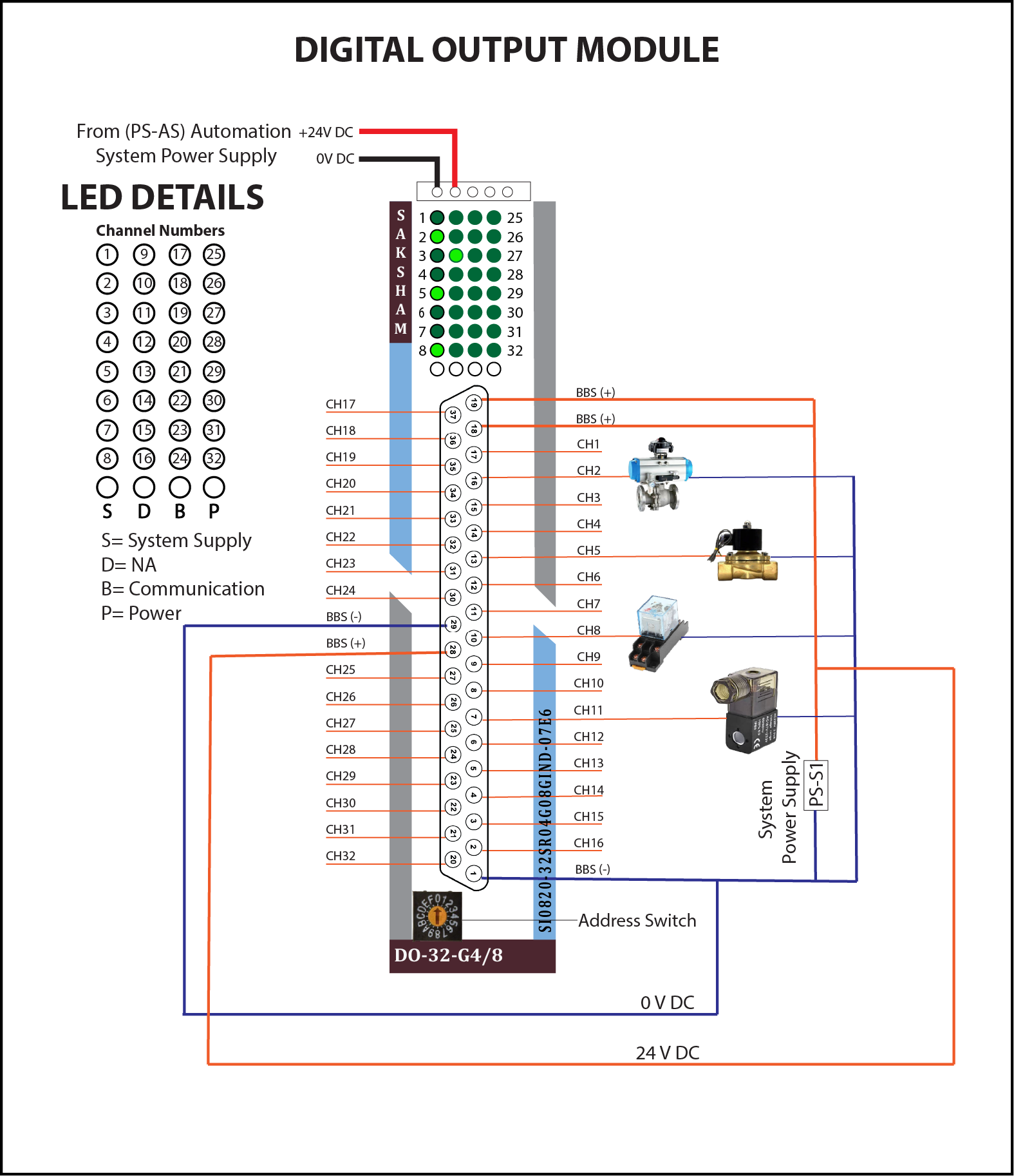
This guide explains how to wire and configure the DO-32-G4/8 Digital Output Module for controlling devices like solenoids, relays, and lamps in TPW-Saksham control systems.
DO-32-G4/8 Digital Output Module – Wiring Description
Whay is a DO Module?
This 32-channel digital output module controls external devices with precision, offering galvanic isolation in 2 groups for superior reliability, efficiency, and safety in industrial automation systems.
Power Supply
- +24V DC: Supplied to the field devices through the BBS(+) terminals.
- 0V DC: Connected via BBS(–) terminals for return path.
- These terminals power the output loads such as solenoids, relays, etc.
- Internal System Power is supplied separately via the top connector for module operation.
Output Wiring Groups
CH1 to CH16:
- Each channel drives a field device directly.
- Devices include solenoid valves, relays, and indicator lamps.
- All outputs are powered via the BBS(+) terminal and return through BBS(–).
CH17 to CH32:
- These additional output channels are also connected to field actuators.
- Uses similar power routing through BBS terminals.
LED Indicators
Each channel has an individual LED that indicates the output status.
LED Symbols:
- S: System Supply
- D: Not Applicable
- B: Communication
- P: Power
⚠️ Important Notes:
- BBS(+) should be connected to the +24V DC supply for output load.
- BBS(–) must be connected to 0V DC.
- Make sure field devices are rated for 24V operation.
- Use external protection (e.g., fuses or snubbers) for inductive loads like solenoids or motors.
Address Switch Configuration
What is an Address Switch?
The Address Switch is a built-in rotary switch on the Saksham module. Its purpose is to assign a unique identification number (address) to the module. This address allows the system's Interface Module (IM) or CPU to correctly identify and communicate with the module over the backplane (TBUS).
Each module in the system must have a distinct address to ensure proper data flow and avoid conflicts.
How Does the Address Switch Work?
- The address you assign using the switch must match the module address configured in your PLC program.
- You set the switch by rotating it using a small screwdriver.
Example Mapping:
| Module Address | Hex Value | Rotary Switch Position |
|---|---|---|
| 1000 | 03E8 | 0 |
| 2000 | 07D0 | 1 |
| 3000 | 0BB8 | 2 |
| 4000 | 0FA0 | 3 |
| 5000 | 1388 | 4 |
| 6000 | 1770 | 5 |
| 7000 | 1B58 | 6 |
| 8000 | 1F40 | 7 |
📝 Note: The system reads this hardware address during startup or communication initialization to map and manage each module correctly.
⚠️ Important Guidelines:
- Ensure each module has a unique address — duplicate addresses can cause communication failures.
- After setting the address, verify that it matches your software configuration.
Safety & Best Practices
- Avoid shorting output terminals
- Double-check wiring against diagrams
- Properly label all connected cables for troubleshooting