Visualization Documentation – MOTOR Block
Usage of MOTOR Block through SCADA Template
The MOTOR block provides control and monitoring of unidirectional motors such as pumps, fans, or conveyors.
In the SCADA Template system, it is used as a reusable visualization component, enabling runtime operation, monitoring, configuration, and diagnostics.
This block is integrated via a template-based visualization structure. The graphical icon is pre-configured and reused from the Scada_test Visu Page.
- Use the MOTOR block icon in any custom visualization page and link it to its corresponding logic instance.
Integrating the MOTOR Block into Visualization
1. Open Your Visualization Page
- Open your CODESYS project.
- Navigate to the desired HMI screen (e.g.,
Main_HMI,Pump_Control, etc.).
2. Insert the MOTOR Block Icon from Scada_test Visu Page
- Open the Visualization Toolbox Go to Current Project.
- Drag or drop the MOTOR Block icon to your Visualization page.
- Or Just Copy the MOTOR Block Icon from the
Scada_testvisu page and Paste into your Visualization page.
✅ Promotes standardization and template reusability.
3. Link the MOTOR Block to Its Logic Instance
- Select the inserted MOTOR block icon.
- click on the block icon Properties tab open automatically → Properties.
- Go to the References and Expand the references.
- you will see bl_motor_L_1d or bl_motor_R_1d or bl_motor_T_1d or bl_motor_T_1d_R Expand that also.
- set the path in front of the tagMotor_fp by Double clicking on empty space and select the required tag.
- Build and run the project.
- During runtime, confirm the motor responds and displays correct feedback.
MOTOR Block Icon – Status Indicators
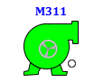
- On Clicking Motor Block Icon Faceplate opens.
The motor icon shows real-time status through color-coded visuals
Motor Faceplate Overview
Clicking the MOTOR block opens a faceplate with four tabs:
- Operator Tab – Runtime control
- Basic Tab – Operational summary
- Advance Tab – Engineering configuration
- Diagnostics Tab – Feedback and alarms
Faceplate - Operator Tab
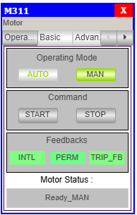
Operating Modes
- AUTO: Controlled via PLC logic.
- MAN: Operated via HMI.
Active mode is highlighted in green.
Commands
- START: Start the motor (manual mode only).
- STOP: Stop the motor (manual mode only).
Feedbacks
| Signal | Description |
|---|---|
| INTL | Interlock status |
| PERM | Start permission |
| Trip | Fault or trip status |
Motor Status
- Displays the current state, e.g.,
Ready_MAN,Running_AUTO.
Faceplate - Basic Tab
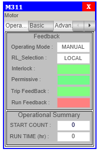
Feedbacks
| Parameter | Description |
|---|---|
| Operating Mode | Current control mode |
| RL_Selection | Remote or Local mode |
| Interlock | Interlock condition |
| Permissive | Permission status |
| Trip Feedback | Fault/trip indication |
| Run Feedback | Whether motor is running |
Operational Summary
- START COUNT: Number of starts
- RUN TIME: Accumulated motor runtime
Faceplate - Advance Tab
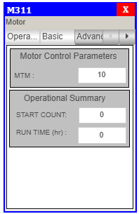
Motor Control
- MTM: Motor Timer Management value
Operational Summary
- START COUNT and RUN TIME shown again for quick access
Faceplate - Diagnostics Tab
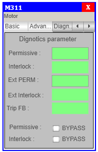
Diagnostic Parameters
| Label | Description |
|---|---|
| Permissive | Internal permission |
| Interlock | Internal interlock |
| Ext Perm | External permissive condition |
| Ext Interlock | External interlock condition |
| Trip Feedback | Fault/trip feedback |
Additional Notes
- ✅ Bypass checkboxes are available for Permissive and Interlock in Diagnostic tab.
- 🛡️ Use access roles to restrict bypass functionality to engineers or authorized users.
Integration Tips
- Always assign the correct Element Variable for logic reference.
- Test manual/auto mode toggling during commissioning.
- Use alarm banners to capture trip or interlock issues in runtime.
Summary
The MOTOR block is a reusable, visual motor control interface in the TPW SCADA system.
✅ Supports real-time motor status and control
✅ Faceplate with Operator, Basic, Advance & Diagnostic tabs
✅ Color-coded visual feedback
✅ Easy integration with drag-and-drop structure
✅ Bypass and simulation supported for maintenance
Ensures reliable and safe motor operation in industrial automation scenarios.