PID_ET Block Documentation
Overview
The PID_ET block is an advanced Proportional-Integral-Derivative (PID) controller equipped with External Tuning capabilities and integrated alarm management with acknowledgment. It is specifically designed for precise process control where dynamic adjustment and clear visualization of control behavior and process deviations are required.
- Real-Time Process Monitoring
Displays Process Variable (PV), Setpoint (SP), and Controller Output (OUT) in real time.
Block Icon
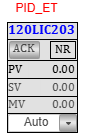
| Element | Description |
|---|---|
| 1. Tag Number (Red Font) | Displays the process tag (e.g., 120PT101) in red for easy identification. Clicking the tag opens the faceplate. |
| 2. Acknowledge Button (ACK) | Used to acknowledge active alarms. Once acknowledged, the blinking in the alarm window stops. |
| 3. Alarm Status Window | Visually indicates the current alarm state of the process (blinking if active and not acknowledged). |
Note: On Clicking the PID-ET block icon, the corresponding faceplate below will be displayed.
Faceplate Tabs
Basic Level Tab
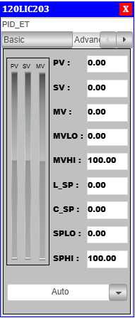
PID Basic Faceplate Description
- PV (Process Variable): Real-time value from sensor.
- SV (Setpoint Value): Target value set for process control.
- MV (Manipulated Value): PID controller output.
- MVLO (Min MV): Minimum value allowed for manipulated output.
- MVHI (Max MV): Maximum value allowed for manipulated output.
- L_SP (Local Setpoint): Local setpoint value.(Given by Operator)
- C_SP (Cascade Setpoint): Cascade setpoint reference.(Calculated setpoint)
- SPLO: Lower override limit for setpoint.
- SPHI: Upper override limit for setpoint.
Advanced Level Tab
On clicking the Adva button, the Adva Tab will open.
Only authorized users can access this after logging in.
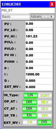
PID Advanced Faceplate Description
Control Mode & Action Selection
- Output Action (OP_AT): Sets the controller output to Direct (DIR) or Reverse (REV).
- Control Action (CT_AT): Defines the internal control mode as Direct (DIR) or Reverse (REV).
- Setpoint Tracking (SP_TR): Enables (EN) or disables (DIS) setpoint tracking.
Alarm & Process Variables
- PV: Real-time process variable value.
- PV_LO: Low limit for process variable.
- PV_HI: High limit for process variable.
- PVLL: Very low alarm threshold.
- PVLO: Low alarm threshold.
- PVHI: High alarm threshold.
- PVHH: Very high alarm threshold.
PID Tuning Parameters
- P (Proportional Gain): Controls response to present error.
- I (Integral Time): Eliminates accumulated error over time.
- D (Derivative Time): Predicts future error based on rate of change.
Process Variable Limits
- PVHH: Critical upper process variable limit.
- PVHI: Warning-level high limit.
- PVLO: Warning-level low limit.
- PVLL: Critical lower process variable limit.
Faceplate Interface & Navigation
- Tag Number: Shows PID block tag (e.g.,
120HBP101). - Toggle Switches & Action Buttons: Used for mode switching.
- Tuning Adjustment Section: Area for modifying P, I, D values.
- Action Mode Indicators (Green Highlight): Indicates currently active state.
Alarm Handling Logic
The PID-ET block includes robust alarm handling features for process safety and operator awareness. The alarm window behavior is as follows:
Low Alarm
- When a Low Alarm occurs:
- The alarm window starts blinking to indicate an active alarm.
- When the Acknowledge (ACK) button is pressed:
- The alarm is acknowledged.
- The blinking stops.
Very Low Alarm
- When a Very Low Alarm occurs:
- The alarm window starts blinking to indicate an active alarm.
- When the ACK button is pressed:
- The alarm is acknowledged.
- The blinking stops.
High Alarm
- When a High Alarm occurs:
- The alarm window starts blinking to indicate an active alarm.
- When the ACK button is pressed:
- The alarm is acknowledged.
- The blinking stops.
Very High Alarm
- When a Very High Alarm occurs:
- The alarm window starts blinking to indicate an active alarm.
- When the ACK button is pressed:
- The alarm is acknowledged.
- The blinking stops.
The ACK button is essential for managing active alarms and restoring a clear view on the HMI after operator intervention.
Typical Use Case
- Applications requiring visual alarm signaling, manual acknowledgment, and priority visibility in the HMI.
- Enhances operator awareness and response time for critical PV deviations.
Integration Guidelines
- Place the PID_ET block icon in the visualization screen.
- Use the Reference property in the HMI tool to connect the faceplate with the block instance.
- Ensure alarm limits (PV_LL, PV_LO, PV_HI, PV_HH) are correctly configured in the logic or data block.
- Use standard alarm tags for SCADA linkage or logging.