PID-MR Block Documentation
Overview
The PID-MR (Modular PID with Manual Reset) block includes a Manual Reset (MR) functionality designed for situations where operator intervention is required before the controller resumes normal automatic operation. This feature enhances safety and control reliability in critical process loops.
Behavior of Manual Reset
- When the Manual Reset (MR) condition is active, the block halts automatic PID output control.
- If External MV Enable (EXT_MV_EN) is set to
TRUE, the block bypasses internal PID computation and directly passes the External MV (EXT_MV) value to the Output (OUT).
Block Icon
| Element | Description |
|---|---|
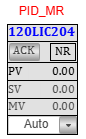
| 1. Tag Number (Red Font) | Displays the process tag (e.g., 120LIC101) in red font. Clicking on the tag opens the detailed PID-MR faceplate. |
| 2. Acknowledge Button (ACK) | Used to acknowledge active alarms. After acknowledgment, the alarm blinking stops. |
| 3. Alarm Status Window | Displays the current alarm status. When an alarm is active and unacknowledged, this window blinks as a warning. |
Note: On Clicking the PID-MR block icon, the corresponding faceplate below will be displayed.
Faceplate Tabs
Basic Level Tab
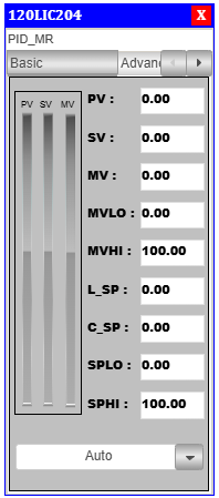
PID Basic Faceplate Description
- PV (Process Variable): Real-time value from sensor.
- SV (Setpoint Value): Target value set for process control.
- MV (Manipulated Value): PID controller output.
- MVLO (Min MV): Minimum value allowed for manipulated output.
- MVHI (Max MV): Maximum value allowed for manipulated output.
- L_SP (Local Setpoint): Local setpoint value.
- C_SP (Cascade Setpoint): Cascade setpoint reference.
- SPLO: Lower override limit for setpoint.
- SPHI: Upper override limit for setpoint.
Advanced Level Tab
On clicking the Adva button, the Adva Tab will open.
Only authorized users can access this after logging in.
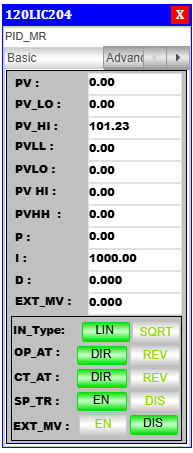
PID Advanced Faceplate Description
Control Mode & Action Selection
- Output Action (OP_AT): Sets the controller output to Direct (DIR) or Reverse (REV).
- Control Action (CT_AT): Defines the internal control mode as Direct (DIR) or Reverse (REV).
- Setpoint Tracking (SP_TR): Enables (EN) or disables (DIS) setpoint tracking.
Alarm & Process Variables
- PV: Real-time process variable value.
- PV_LO: Low alarm limit for process variable.
- PV_HI: High alarm limit for process variable.
- PVLL: Very low alarm threshold.
- PVLO: Low alarm threshold.
- PVHI: High alarm threshold.
- PVHH: Very high alarm threshold.
PID Tuning Parameters
- P (Proportional Gain): Controls response to present error.
- I (Integral Time): Eliminates accumulated error over time.
- D (Derivative Time): Predicts future error based on rate of change.
Process Variable Limits
- PVHH: Critical upper process variable limit.
- PVHI: Warning-level high limit.
- PVLO: Warning-level low limit.
- PVLL: Critical lower process variable limit.
Faceplate Interface & Navigation
- Tag Number: Shows PID block tag (e.g.,
120LIC101). - Toggle Switches & Action Buttons: Used for mode switching.
- Tuning Adjustment Section: Area for modifying P, I, D values.
- Action Mode Indicators (Green Highlight): Indicates currently active state.
Alarm Handling Logic
The PID-MR block includes robust alarm handling features for process safety and operator awareness. The alarm window behavior is as follows:
Low Alarm
- When a Low Alarm occurs:
- The alarm window starts blinking to indicate an active alarm.
- When the Acknowledge (ACK) button is pressed:
- The alarm is acknowledged.
- The blinking stops.
Very Low Alarm
- When a Very Low Alarm occurs:
- The alarm window starts blinking to indicate an active alarm.
- When the ACK button is pressed:
- The alarm is acknowledged.
- The blinking stops.
High Alarm
- When a High Alarm occurs:
- The alarm window starts blinking to indicate an active alarm.
- When the ACK button is pressed:
- The alarm is acknowledged.
- The blinking stops.
Very High Alarm
- When a Very High Alarm occurs:
- The alarm window starts blinking to indicate an active alarm.
- When the ACK button is pressed:
- The alarm is acknowledged.
- The blinking stops.
The ACK button is essential for managing active alarms and restoring a clear view on the HMI after operator intervention.
Use Case & Integration
- Ideal for critical PID loops that require manual reset features after alarm events.
- Used where the operator must validate and acknowledge process alarms before continuing operations.
Integration Steps
- Insert the PID-MR block icon into the visualization.
- Set the reference to the respective logic block via the References panel.
- Configure the alarm limits (PV_LL, PV_LO, PV_HI, PV_HH) within the logic.
- Link with SCADA system if extended alarm handling is needed.