Analog Input (AI) Module – Wiring Diagram
Introduction
This guide shows how to wire the AI-16-G4/8 Analog Input Module, which reads signals from sensors and transmitters. Isolated channel groups ensure accuracy and reliability. Follow for safe and proper PLC connections.
1. AI-16-G4/8 Analog Input Module – Wiring Description
What is an AI Module?
This 16-channel analog input module enables precise monitoring by integrating analog signals from various devices, featuring galvanic isolation across four groups for enhanced reliability in PLC systems.

Group-wise Terminal Assignment
| Group | Channels | 0VDC Terminal |
|---|---|---|
| 1 | AI1 to AI4 | 11 no. terminal for Group 1 |
| 2 | AI5 to AI8 | 1 & 2 no. terminal for Group 2 |
| 3 | AI9 to AI12 | 29 no. terminal for Group 3 |
| 4 | AI13 to AI16 | 20 no. terminal for Group 4 |
Key Features:
- Supports 16 Analog Input channels
- Divided into 4 groups of 4 channels each
- Each group has its own 0V (Ground) terminal for signal isolation
- Designed for both loop-powered field instruments (24VDC) and 4-wire signals
Power Connection
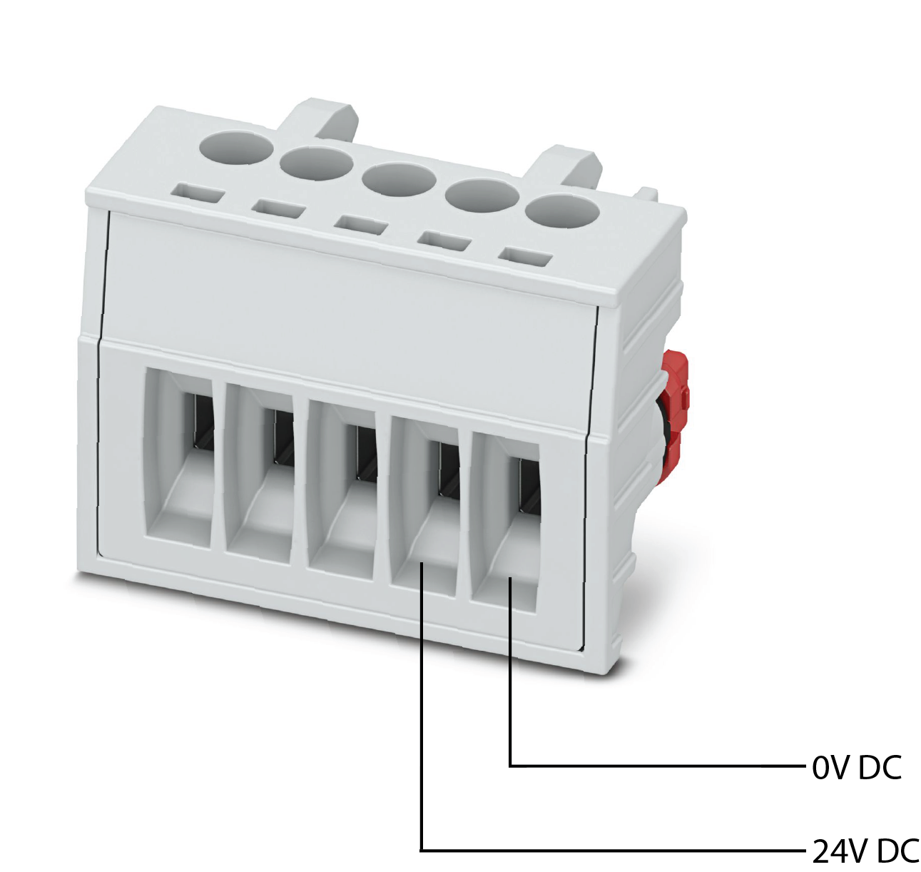
Connect a regulated 24VDC power supply to the top power terminals:
- +24VDC ➝ Positive terminal
- 0VDC ➝ Negative/Return terminal
-
Wiring Analog Input Devices (like transmitters)
-
Each input device has two wires — one (+) and one (−)
Follow these steps:
-
Identify the correct input channel (e.g., AI1, AI2…AI16).
-
Connect the (+) wire of the field device to the AIx(+) terminal.
-
Connect the (−) wire to the common 0VDC terminal of that group.
✅ Each group is electrically isolated.
❌ Do NOT cross-connect 0V terminals between groups.
Wiring Tips
- Use shielded twisted pair cables for analog signals.
- Keep analog wires away from high-voltage and power lines.
- Strip wire ends ~7 mm and use ferrules for a neat connection.
- Ensure terminals are tightened properly (torque: 0.5–0.6 Nm).
LED Indicators
- B (Communication): Blinks when communicating with IM, steady glow when not communicating
- P (Power): Glows when power is ON
- F (Fault): Glows when a fault occurs
Address Switch Configuration
What is an Address Switch?
The Address Switch is a built-in rotary switch on the Saksham module. Its purpose is to assign a unique identification number (address) to the module. This address allows the system's Interface Module (IM) or CPU to correctly identify and communicate with the module over the backplane (TBUS).
Each module in the system must have a distinct address to ensure proper data flow and avoid conflicts.
How Does the Address Switch Work?
- The address you assign using the switch must match the module address configured in your PLC program.
- You set the switch by rotating it using a small screwdriver.
Example Mapping:
| Module Address | Hex Value | Rotary Switch Position |
|---|---|---|
| 1000 | 03E8 | 0 |
| 2000 | 07D0 | 1 |
| 3000 | 0BB8 | 2 |
| 4000 | 0FA0 | 3 |
| 5000 | 1388 | 4 |
| 6000 | 1770 | 5 |
| 7000 | 1B58 | 6 |
| 8000 | 1F40 | 7 |
📝 Note: The system reads this hardware address during startup or communication initialization to map and manage each module correctly.
⚠️ Important Guidelines:
- Ensure each module has a unique address — duplicate addresses can cause communication failures.
- After setting the address, verify that it matches your software configuration.
Safety & Best Practices
- Avoid shorting output terminals
- Double-check wiring against diagrams
- Properly label all connected cables for troubleshooting