AO FTA Wiring Diagram
Wiring Diagram – AO FTA (Analog Output Field Terminal Assembly)
What is AO FTA?
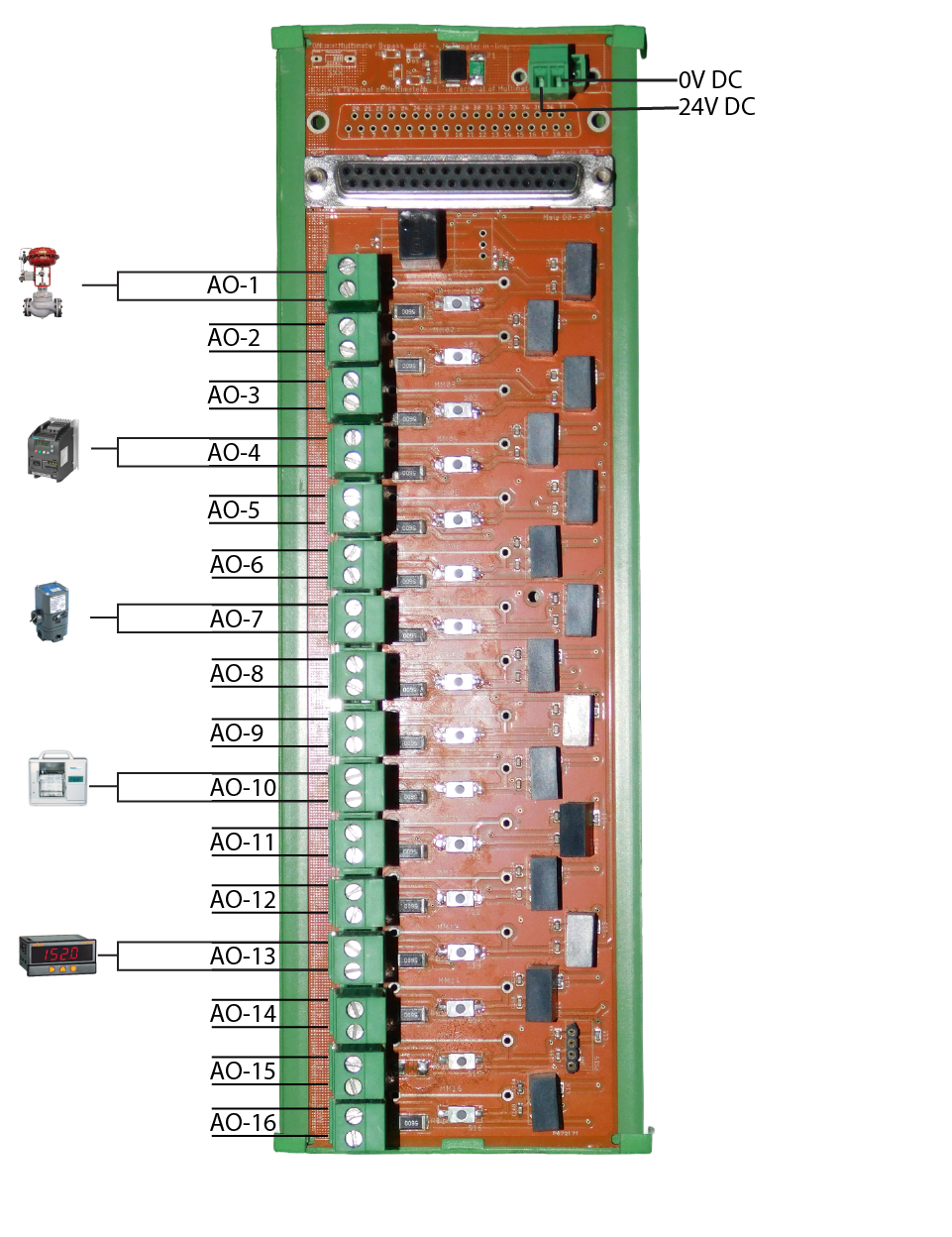
The AO FTA (Analog Output Field Terminal Assembly) helps connect the analog output module of the PLC to field devices like control valves and I/P converters. It makes wiring easier, neater, safer, and improves troubleshooting, efficiency, and maintenance access.
PLC Connection
The AO FTA connects to the PLC using a Prefabricated 37-pin D-sub Cable. This cable carries all 16 Analog Output signals.
Field Device Connection
- For each of the 16 output channels, there are screw terminals labeled +ve, -ve, and GND.
- You can directly connect field devices here.
Power Supply
- AO FTA works with 24V DC.
- Make sure the power is stable and the current does not exceed 0.5 A in total or 20 mA per channel.
Wiring Tips
- Use proper wire sizes:
- For normal (rigid) wire:
0.2 mm² to 2.5 mm² - For flexible wire:
0.2 mm² to 1.5 mm² (signal)and up to2.5 mm² (power) - Tighten the screws with care:
- Use torque between 0.5 Nm to 0.6 Nm to avoid damage.
- Mount the FTA on a DIN rail in any position inside the control panel.
Environment
- Temperature range:
-20°C to 70°C - Max height:
2000 metersabove sea level - Use inside a panel that provides at least IP54 protection from dust and moisture.
Easy Testing
- This FTA allows you to test your field wiring without removing wires.
- Just use a multimeter and the test push buttons provided on the FTA board.