LIN10P (10-Point Linearization Block Documentation)
Overview
The LIN10P block is a functional component used in industrial automation systems to convert non-linear analog inputs into linearized outputs using a predefined set of reference (X, Y) points. It enables improved accuracy for devices such as pressure, level, or flow transmitters that exhibit non-linear characteristics.
- The logic performs piecewise linear interpolation using up to 10 configurable (X, Y) pairs.
- It significantly improves measurement accuracy, simplifies control logic, and enhances system stability and reliability.
- LIN10P is especially useful where high-precision scaling of sensor data is needed prior to display or control action.
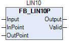
Logic Block Illustration
The FB_LIN10P block provides a clear method to linearize raw analog input from field instruments.
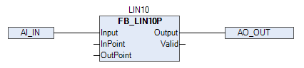
A visual representation of the LIN10P logic block in the programming environment.
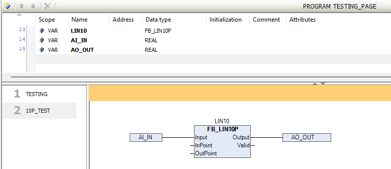
The above image illustrates how to connect the LIN10P block within logic for input signal scaling.
Pins Information
| Signal | Type | Description |
|---|---|---|
Input |
REAL | The raw process value to be linearized. |
InPoint |
ARRAY[1..10] OF REAL | X-axis reference points (raw sensor values). Must be in ascending order. |
OutPoint |
ARRAY[1..10] OF REAL | Y-axis scaled output values corresponding to each InPoint. |
Output |
REAL | Interpolated and scaled output value. |
Valid |
BOOL | TRUE if valid interpolation is performed (i.e., at least 2 valid points). |
Operational Summary
- The block checks where the
Inputvalue lies between any two adjacentInPointvalues. - It then performs linear interpolation using the corresponding
OutPointvalues. - If input falls outside the configured range or fewer than two points are valid, the output is marked invalid via the
Validbit. - This block has no faceplate. It is typically used internally with other logic and analog scaling blocks.
Example Use Cases
- Converting a non-linear tank level (mm) to actual volume (liters).
- Compensating for non-linearity in differential pressure-based flow measurement.
- Custom calibration curves for unusual sensors.
Training Demo Video
Demonstration video is available , How to use the Daca Logic Block through Library:
LIN10P Block Demo - TPW Logic Setup
Best Practices
- Ensure InPoint values are strictly increasing (ascending) to prevent logic errors.
- Do not use duplicate X-values in
InPointarray. - Always check
Validoutput before usingOutputin downstream logic.
Tip:
This block is ideal for compensating non-linear device behavior in critical process loops where precision and repeatability are essential.