Manual Loader (MLD) Block Documentation
Overview
The Manual Loader (MLD) is a control block that enables operators to override automatic control signals and apply manual outputs when required. It is particularly useful during plant commissioning, maintenance, fault isolation, or testing scenarios.
MLD operates in two modes:
- Auto Mode: Input signal is passed directly to the output.
- Manual Mode: Operator-defined value (
M_OP) is used as the output.
This block ensures safe switching between modes, including enforced output limits to prevent unsafe conditions during manual operation.
Block Icon
 Manual loader in auto mode.
 Manual loader in manual mode.
On Clicking the blue tagname of Manual loader block icon, the associated faceplate opens, providing detailed control and status parameters.
Block Icon Behavior
| No. | Element | Description |
|---|---|---|
| 1 | Tag Number (Blue Area) | Clickable tag number that opens the detailed MLD faceplate. |
| 2 | Mode Indicator | Displays whether the block is in Auto (A) or Manual (M) mode. |
| 3 | Output Display | Shows the current output based on the selected mode. |
| 4 | Status Feedback | Provides feedback for current control conditions or errors if any. |
Faceplate Description
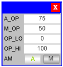
| Field | Description |
|---|---|
| A_OP (Auto Output) | Process signal received at the input. It becomes the block's output in Auto mode. |
| M_OP (Manual Output) | Operator-defined output used in Manual mode. |
| OP_LO (Low Limit) | Lower boundary for M_OP. Prevents unsafe low outputs. |
| OP_HI (High Limit) | Upper boundary for M_OP. Prevents unsafe high outputs. |
| AM (Auto/Manual Toggle) | Switch used to change the control mode between Auto and Manual. |
Important: Manual output (
M_OP) is only used when the mode is explicitly set to Manual. In Auto mode, manual values have no effect.
Operating Modes
Auto Mode
- Default operational mode.
A_OP(input value) is directly transferred to the output.- Ideal for routine process control, driven by logic or sensors.
Manual Mode
- Output is decoupled from the input.
- Operator sets the output using
M_OP. - Commonly used during:
- Field testing
- Output calibration
- Failure of upstream signals
- Manual interventions
Safety Limits and Output Protection
Manual outputs are confined within predefined high and low limits:
| Parameter | Function |
|---|---|
| OP_LO | Minimum allowed manual output value |
| OP_HI | Maximum allowed manual output value |
These boundaries are crucial for maintaining safe operation and protecting actuators or process units from invalid values.
Usage Example
Scenario: A pump control signal is fluctuating due to sensor fault.
-
Switch the Manual Loader to Manual Mode.
-
Enter a stable value in
M_OPto maintain output. -
Set limits
OP_LO = 10,OP_HI = 90to avoid overdriving the pump. -
Once the sensor is fixed, switch back to Auto Mode.
Operator Guidelines
- Operators are allowed to view the faceplate and toggle Auto/Manual mode only if permission is granted.
- Engineers or technicians should configure
OP_LO,OP_HI, and validateM_OPvalues. - Safety interlocks or supervisory controls may restrict unauthorized Manual Mode access.
Notes
- Always validate limits before applying manual output.
- Avoid switching modes frequently during transient process conditions.
- Combine MLD blocks with alarms for robust manual override strategy.