IO Module Installation and Configuration Manual
INTRODUCTION
This manual provides step-by-step guidance for the installation of I/O modules in the Saksham PLC system. It is intended to help users safely and accurately complete the mechanical setup of I/O hardware components.
In this section, we will focus exclusively on:
- Installation of the T-BUS (Terminal Bus)
- Mounting of I/O Modules (AI, AO, DI, DO)
Hardware Components to be Installed
- T-BUS
- Modules
Installation of T-BUS
- ✅ A T-BUS is a small connector that goes under each PLC module.
- ✅ It carries signals between the modules.
- ✅ It saves wiring effort and makes the system neat and easy to expand.
Why TBUS is Important?
| Feature | Without T-BUS | With T-BUS |
|---|---|---|
| Communication | Manual connections or wiring | Shared via T-BUS pins |
| Installation Time | Slower and error-prone | Fast and tool-free |
| Panel Appearance | Messy and hard to manage | Clean and organized |
| Future Expansion | Complicated re-wiring needed | Just slide in another module on T-BUS |
Installation Steps OF T-BUS
Step 1: Insert the First T-BUS Connector
- Take a T-BUS connector and place it on the DIN rail.
- Hook one side of the T-BUS onto the top edge of the DIN rail.
- Then press down gently until it clicks into place.
- The metal pins should face upward – these will connect with your modules.
📝 Tip: You don’t need to use any screws. It simply clips on.
Step 2: Add More T-BUS Connectors (Max. 9 T-BUS)
- Place a second T-BUS connector right next to the first one.
- Make sure the ends of both connectors touch each other – there should be no gap.
- Repeat this for all the modules you plan to install (one T-BUS per module).
✅ Check: All T-BUS connectors should be aligned and form one straight line.
Step 3: Double-Check Alignment
Look from the top to ensure all T-BUS pieces are:
- Tightly placed on the DIN rail
- Perfectly connected end-to-end
- No connectors are loose or misaligned
🛑 Warning: Misalignment can prevent modules from getting signal.
Step 4: Secure the Ends (Optional)
- Once all T-BUS connectors are in place, you can install END CLAMP at both ends.
- The DIN RAIL on which the module rack is to be mounted should be installed using a panel isolator, and the DIN RAIL should be connected to the panel's power earth. This enhances the safety of the module.
This helps to:
- Keep the T-BUS in place
- Maintain a neat finish
Step 5: Done
Your T-BUS installation is now complete.
You can now begin placing the modules on top of the T-BUS.

🧯 Safety Tips
- Handle T-BUS connectors gently — avoid bending the pins.
- Don’t leave gaps between T-BUS connectors.
- Only use T-BUS connectors compatible with your PLC system.
Installation Steps OF IOs
Step 1: Install the IM Module (Interface Module)
Start by fixing the IM module on the leftmost side of the DIN rail.
This is always the first module to be installed.
How to install:
- Place the IM module on the left side of the DIN rail.
- Align it properly with the rail and press it in.
- You’ll hear a click when it locks in place.
- Make sure it is firmly attached and not loose.
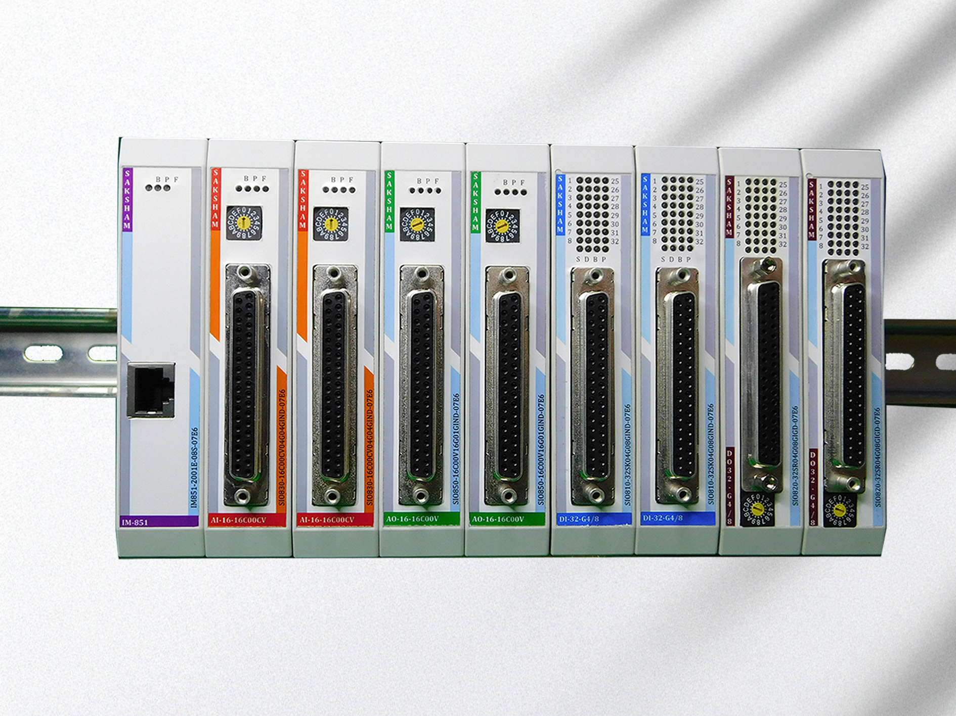
Step 2: Install I/O Modules to the Right of IM
Once the IM module is in place, install all other I/O modules on the right side of it.
You can install them in any order – Digital Input, Digital Output, Analog Input, etc.
How to install:
- Take the next I/O module.
- Line it up with the IM module (side-to-side connection).
- Also align it with the DIN rail below.
- Push it in until it clicks and locks into place.
- Repeat this for all remaining I/O modules.
Final Check
Make sure:
-
All modules are tight and properly connected.
-
There are no gaps between modules.
-
Each module is locked firmly on the DIN rail.