Digital Input (DI) Module – Wiring Diagram
INTRODUCTION
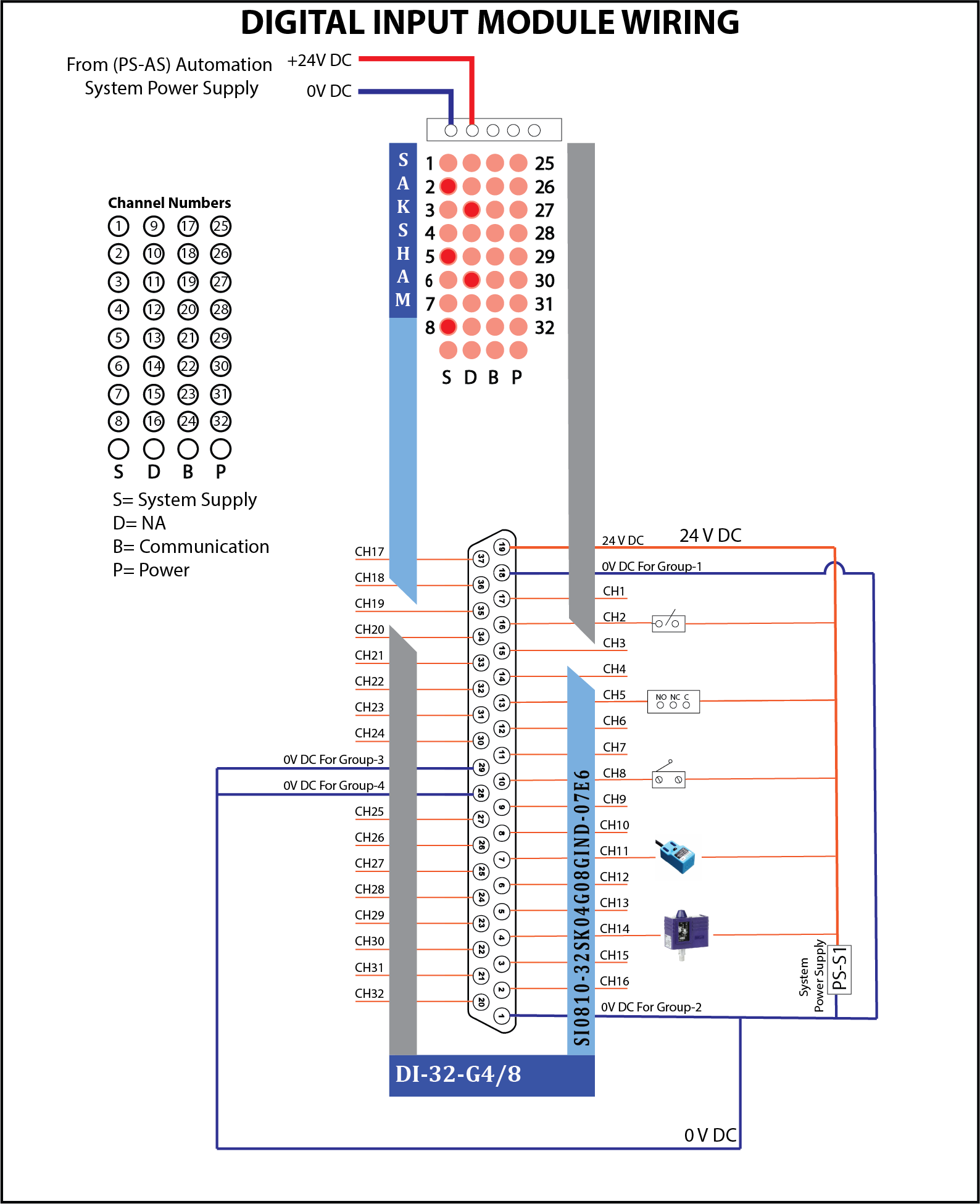
This section provides wiring and address setup for the DI-32-G4/8 Digital Input Module. With galvanic isolation, it ensures reliable, high-speed input from sensors, switches, and field devices in Saksham PLC-based industrial systems.
DI-32-G4/8 Digital Input Module – Wiring Description
What is a DI Module?
This 32-channel digital input module ensures accurate data acquisition from field devices, with galvanic isolation in 4 groups for enhanced performance and reliability in industrial automation systems.
Power Supply
- +24V DC: Supplied to power the module
- 0V DC: Separate return lines for each group:
| Group | Channels | 0V DC Terminal |
|---|---|---|
| Group 1 | CH1–CH8 | Terminal 18 |
| Group 2 | CH9–CH16 | Terminal 1 |
| Group 3 | CH17–CH24 | Terminal 29 |
| Group 4 | CH25–CH32 | Terminal 28 |
Wiring Structure
- Group 1 (CH1 to CH8):
- Connected to field digital input devices like switches/sensors.
-
All channels share one 0V DC return line (Group 1).
-
Group 2 (CH9 to CH16):
- Connected similarly to field devices.
-
Uses its own 0V DC return line (Group 2).
-
Group 3 (CH17 to CH24):
- Field devices are connected to CH17–CH24.
-
Uses 0V DC return line for Group 3.
-
Group 4 (CH25 to CH32):
- Field devices connected here.
- Uses 0V DC return line for Group 4.
LED Indicators
Each channel has an individual LED indicator showing the input signal status.
- S: System Supply
- D: Not Applicable
- B: Communication
- P: Power
Address Switch Configuration
What is an Address Switch?
The Address Switch is a built-in rotary switch on the Saksham module. Its purpose is to assign a unique identification number (address) to the module. This address allows the system's Interface Module (IM) or CPU to correctly identify and communicate with the module over the backplane (TBUS).
Each module in the system must have a distinct address to ensure proper data flow and avoid conflicts.
How Does the Address Switch Work?
- The address you assign using the switch must match the module address configured in your PLC program.
- You set the switch by rotating it using a small screwdriver.
Example Mapping:
| Module Address | Hex Value | Rotary Switch Position |
|---|---|---|
| 1000 | 03E8 | 0 |
| 2000 | 07D0 | 1 |
| 3000 | 0BB8 | 2 |
| 4000 | 0FA0 | 3 |
| 5000 | 1388 | 4 |
| 6000 | 1770 | 5 |
| 7000 | 1B58 | 6 |
| 8000 | 1F40 | 7 |
📝 Note: The system reads this hardware address during startup or communication initialization to map and manage each module correctly.
⚠️ Important Guidelines:
- Ensure each module has a unique address — duplicate addresses can cause communication failures.
- After setting the address, verify that it matches your software configuration.
Safety & Best Practices
- Avoid shorting output terminals
- Double-check wiring against diagrams
- Properly label all connected cables for troubleshooting