Power Connection on Modules
Introduction
This section explains how to properly connect a 24VDC power supply to the Saksham PLC system, including the IM (Interface) module and all connected I/O modules. A correct and secure power connection is essential for the stable and reliable operation of the entire system.
Follow these steps to ensure safe and proper wiring for all modules.
Step 1: Locate the Power Terminals
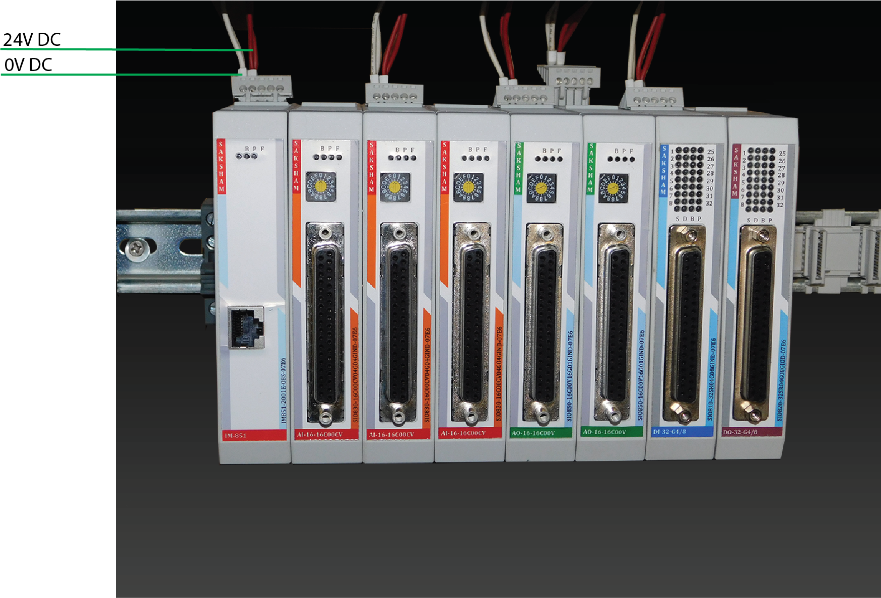
- On the main interface module (IM), identify the power input terminals:
+24VDC→ for the positive supply wire0VDC→ for the negative or ground wire
📌 These terminal labels are usually printed near the connection points or can be found in the module's datasheet.
Step 2: Connect the Power Supply
- Use a regulated 24V DC industrial power supply.
Connect
- The positive (+) wire to the +24VDC terminal
- The negative (−) wire to the 0VDC terminal
⚠️ Ensure the power supply includes short-circuit protection to prevent damage during faults.
Step 3: Check the Wiring
Before powering up, make sure:
- All wire connections are tight and secure
- The polarity is correct (
+to+24VDC,−to0VDC) - There are no loose wire strands that could cause short circuits
💡 Using ferrules on wire ends is a great practice for safety and neatness.
Step 4: Turn ON the Power
- Turn ON the 24V DC power supply.
-
Verify the following:
-
The Power LED on the module is glowing.
- The LEDs on all I/O modules are also glowing, confirming proper power distribution.