PID Controller Logic Documentation
Overview
A Proportional–Integral–Derivative (PID) controller is a feedback-based control loop mechanism commonly used to manage machines and processes that require continuous control and automatic adjustment.
It is widely applied in industrial control systems and other applications where modulation without human intervention is necessary.
The PID controller automatically compares the desired target value (Setpoint or SP) with the actual value of the system (Process Variable or PV).
The difference (error) between SP and PV, denoted as e(t), is minimized using three components:
- Proportional (P): Corrects based on the present error.
- Integral (I): Eliminates residual steady-state errors by considering past errors.
- Derivative (D): Predicts future error trends to enhance system stability.
The PID controller reduces human error and significantly improves system automation.
PID Logic Block Pins
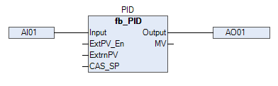
The diagram illustrates the use of the PID Block in the system.
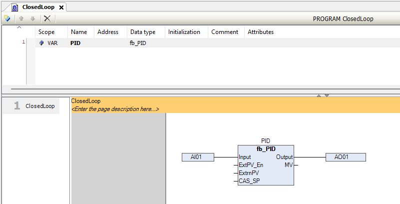
PID Function Block - Pins Information
Below are the detailed input and output signals for the PID block:
| Signal | Type | Description |
|---|---|---|
| INPUT | WORD | Raw input from analog channel |
| PV_LO | REAL | PV low value |
| PV_HI | REAL | PV high value |
| RTN_ACK_REQD | BIT | Configures if Return-To-Normal condition requires acknowledgment |
| ACK | BIT | Alarm acknowledgment input bit |
| Acknowledged | BIT | Alarm acknowledged status output |
| WireBreak | BIT | High when wire break detected (Output) |
| WireShort | BIT | High when wire short detected (Output) |
| PV_LL_ALM | BIT | High when very low PV limit is triggered (Output) |
| PV_LO_ALM | BIT | High when low PV limit is triggered (Output) |
| PV_HI_ALM | BIT | High when high PV limit is triggered (Output) |
| PV_HH_ALM | BIT | High when very high PV limit is triggered (Output) |
| PVLL | REAL | Very low alarm limit (Input) |
| PVLO | REAL | Low alarm limit (Input) |
| PVHI | REAL | High alarm limit (Input) |
| PVHH | REAL | Very high alarm limit (Input) |
| HYST | REAL | Hysteresis value for alarm handling (Input) |
| FILTER | REAL | Filter to mitigate input noise (Input) |
| TagName | STRING(10) | Tag name (Max. 10 characters) (Output) |
| Desc | STRING(12) | Description (Max. 12 characters) (Output) |
| P | REAL | Proportional gain |
| I | REAL | Integral time constant |
| D | REAL | Derivative time constant |
| MVLO | REAL | PID output low limit |
| MVHI | REAL | PID output high limit |
| PID_OP | REAL | Output value in manual mode (%) |
| MODE | BYTE | 0: Manual, 1: Auto, 2: Cascade, 3: Remote |
| Output | WORD | Output value mapped to raw analog output |
| SP_TRACK | BIT | True: SV will track PV |
| CTRL_ACTN | BIT | True: Direct action |
| ExtPV_En | BIT | Enable external PV input |
| ExtrnPV | REAL | External PV value |
| PV | REAL | Process Value |
| SV | REAL | Set Value (Setpoint) |
| MV | REAL | Manipulated Variable (Output %) |
| LOC_SP | REAL | Local setpoint |
| REM_SP | REAL | Remote setpoint |
| CAS_SP | REAL | Cascade setpoint |
| SP_HI_LM | REAL | Setpoint high limit |
| SP_LO_LM | REAL | Setpoint low limit |
| IN_LO | REAL | Output low from program |
| IN_HI | REAL | Output high from program |
| OP_LO | WORD | Low raw output value for AO channel |
| OP_HI | WORD | High raw output value for AO channel |
| DIR | BIT | Output direction: False = Direct, True = Reverse |
| OP_LL_ALM | BIT | High when very low AO limit is triggered (Output) |
| OP_LO_ALM | BIT | High when low AO limit is triggered (Output) |
| OP_HI_ALM | BIT | High when high AO limit is triggered (Output) |
| OP_HH_ALM | BIT | High when very high AO limit is triggered (Output) |
| OPLL | REAL | Very low AO limit (Input) |
| OPLO | REAL | Low AO limit (Input) |
| OPHI | REAL | High AO limit (Input) |
| OPHH | REAL | Very high AO limit (Input) |
| HYST (AO) | REAL | Hysteresis of AO value for alarms (Input) |
Important Notes
- Manual Mode: PID output is directly controlled by the user through
PID_OP. - Auto Mode: PID loop automatically adjusts output based on SP and PV.
- Cascade Mode: SP is received from an upstream controller.
- Remote Mode: SP is received from an external source.
Alarm Handling:
Alarms (PV and OP) are triggered based on configured limits and hysteresis settings. Alarms can be acknowledged manually.External PV (ExtrnPV):
Can be enabled for special cases where the PV must be overridden manually or by another system.
Typical PID Workflow
- Raw analog signal read into INPUT.
- Scaled between PV_LO and PV_HI to calculate PV.
- Controller compares PV with SV.
- Based on P, I, D settings, calculates the output MV.
- Output is constrained within MVLO and MVHI.
- Converts to raw output (Output) for actuator.
Tip:
Tuning PID parameters (P, I, D) properly is crucial for achieving stable and responsive control.