MLD (Manual Loader) Logic Block Documentation
Overview
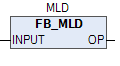
The MLD (Manual Loader) function block is used to manage the flow of analog signals in Auto/Manual selection scenarios. It allows users to manually override an input signal during commissioning, testing, or manual operations.
In Manual Mode, the operator can input a desired value directly using MAN_IN, within defined limits (IN_LO and IN_HI). In Auto Mode, the INPUT signal passes directly to the output, ensuring seamless automation.
This block is particularly useful for systems requiring manual override of analog signals such as setpoints, actuator positions, or control outputs.
Functional Description
- Manual Mode (am_sel = FALSE):
- The operator can manually feed a value through
MAN_IN, limited byIN_LOandIN_HI. -
This mode is useful during testing or commissioning phases.
-
Auto Mode (am_sel = TRUE):
- The external
INPUTvalue is directly routed to theOP(output), bypassing the manual setting.
This block simplifies the switch between auto and manual signal handling in analog control systems.
Showing the MOTOR block in the above picture.
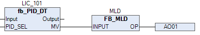
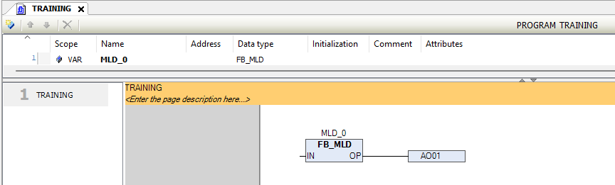
The above picture shows how the inputs and outputs are connected in the MOTOR block.
Input and Output Parameters
| Signal | Type | Description |
|---|---|---|
INPUT |
REAL |
The analog input signal received from external logic or controller |
OP |
WORD |
Output value to be sent to the next process (analog output channel) |
MAN_IN |
REAL |
Manual input value provided by the operator |
IN_LO |
REAL |
Lower limit for manual input |
IN_HI |
REAL |
Upper limit for manual input |
am_sel |
BOOL |
Auto/manual mode selection TRUE = Auto, FALSE = Manual |
Operational Logic
- When
am_sel = FALSE: OP := Clamp(MAN_IN, IN_LO, IN_HI)-
The
MAN_INvalue is constrained within the limits and passed to the output. -
When
am_sel = TRUE: OP := INPUT- The block routes the external signal directly to the output.
Use Case Scenario
- Auto Mode Example:
- Process Setpoint →
INPUT -
OPsends the Setpoint directly to the controller. -
Manual Mode Example:
- Operator sets
MAN_IN= 55.5 IN_LO= 40.0,IN_HI= 60.0OPbecomes 55.5 if within range, else clipped to limits.
Best Practices
- Always configure
IN_LOandIN_HIaccording to system safety constraints. - Display
am_selmode clearly on the HMI for operator awareness. - Log the transitions between Auto and Manual for traceability.
- Use
MLDwhere testing or manual override is frequently required without affecting control loops.
Summary
The MLD block ensures flexibility and control in systems where analog signal override is necessary. It streamlines Auto/Manual signal switching and is highly effective in both process commissioning and normal operations.
Ideal for analog signal override scenarios in critical control systems such as VFD speed control, actuator position control, etc.