PID_DT Controller Logic Documentation
Overview
The PID_DT (Proportional-Integral-Derivative with Dual Tuning) block is an enhanced PID controller designed for advanced process control applications where flexibility, accuracy, and safety are essential.
This block supports two independent sets of PID tuning parameters, making it suitable for processes that require different control characteristics under varying operating conditions (e.g., heating vs. cooling, low vs. high load). It is ideal for use in industrial automation systems that demand robust, responsive, and configurable control logic.
The controller compares the Setpoint (SP) with the Process Variable (PV) and applies PID logic to compute an Output (MV). Features like alarm limits, setpoint tracking, and cascade modes ensure adaptable and safe control.
-
Dual Tuning Modes
Supports two separate sets of PID constants with seamless switching based on operating conditions. -
Adaptive PID Control
Compares the Setpoint (SP) and Process Variable (PV) to calculate the Manipulated Variable (MV) using the selected tuning set. -
Alarm Management
Built-in logic to detect and indicate Very Low, Low, High, and Very High PV alarms. Includes support for operator acknowledgment.
Logic Block Illustration
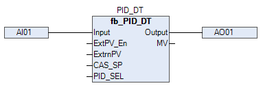
In above picture, we are showing inputs and output of PID-DT block.
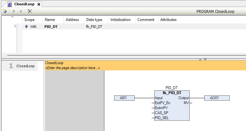
In the above picture, we are showing that how to use the PID-DT block.
PID_DT Block – Pins Information
| Signal | Type | Description |
|---|---|---|
INPUT |
WORD | Raw input from analog channel |
PV_LO |
REAL | PV low scaling range |
PV_HI |
REAL | PV high scaling range |
RTN_ACK_REQD |
BIT | Return-to-Normal condition requires acknowledgment |
ACK |
BIT | Alarm acknowledgment input |
Acknowledged |
BIT | Alarm acknowledgment status output |
WireBreak |
BIT | TRUE when wire break is detected |
WireShort |
BIT | TRUE when wire short is detected |
PV_LL_ALM |
BIT | TRUE when PV falls below very low limit |
PV_LO_ALM |
BIT | TRUE when PV falls below low limit |
PV_HI_ALM |
BIT | TRUE when PV exceeds high limit |
PV_HH_ALM |
BIT | TRUE when PV exceeds very high limit |
PVLL |
REAL | Very low PV alarm limit |
PVLO |
REAL | Low PV alarm limit |
PVHI |
REAL | High PV alarm limit |
PVHH |
REAL | Very high PV alarm limit |
HYST |
REAL | Hysteresis for PV alarm activation/deactivation |
FILTER |
REAL | Filter time constant to reduce PV noise |
TagName |
STRING(10) | PID block tag name (Max. 10 characters) |
Desc |
STRING(12) | Description or label (Max. 12 characters) |
P1 |
REAL | Proportional gain – Day mode |
I1 |
REAL | Integral time constant – Day mode |
D1 |
REAL | Derivative time constant – Day mode |
P2 |
REAL | Proportional gain – Night mode |
I2 |
REAL | Integral time constant – Night mode |
D2 |
REAL | Derivative time constant – Night mode |
DayMode |
BIT | TRUE: Use Day PID; FALSE: Use Night PID |
MVLO |
REAL | Minimum output limit for MV (%) |
MVHI |
REAL | Maximum output limit for MV (%) |
PID_OP |
REAL | Output set manually in manual mode (%) |
MODE |
BYTE | 0: Manual, 1: Auto, 2: Cascade, 3: Remote |
SP_TRACK |
BIT | TRUE: Setpoint follows PV |
CTRL_ACTN |
BIT | TRUE = Direct acting; FALSE = Reverse |
ExtPV_En |
BIT | Enable external PV signal |
ExtrnPV |
REAL | External PV value (used if ExtPV_En is TRUE) |
ExtMV_En |
BIT | Enable external MV signal |
ExtrnMV |
REAL | External MV value (used if ExtMV_En is TRUE) |
LOC_SP |
REAL | Local setpoint |
REM_SP |
REAL | Remote setpoint |
CAS_SP |
REAL | Cascade setpoint |
SP_HI_LM |
REAL | Maximum limit for setpoint |
SP_LO_LM |
REAL | Minimum limit for setpoint |
IN_LO |
REAL | Scaling lower range of analog input |
IN_HI |
REAL | Scaling upper range of analog input |
OP_LO |
WORD | Raw analog output low limit |
OP_HI |
WORD | Raw analog output high limit |
DIR |
BIT | Output direction: FALSE = Direct, TRUE = Reverse |
OPLL |
REAL | Output very low limit |
OPLO |
REAL | Output low limit |
OPHI |
REAL | Output high limit |
OPHH |
REAL | Output very high limit |
HYST (AO) |
REAL | Hysteresis for output alarm handling |
PV |
REAL | Scaled process variable |
SV |
REAL | Active setpoint |
MV |
REAL | Manipulated variable (controller output) |
Output |
WORD | Final output mapped to raw analog value |
OP_LL_ALM |
BIT | TRUE when output is below very low alarm limit |
OP_LO_ALM |
BIT | TRUE when output is below low alarm limit |
OP_HI_ALM |
BIT | TRUE when output is above high alarm limit |
OP_HH_ALM |
BIT | TRUE when output is above very high alarm limit |
Important Notes
- Manual Mode:
PID_OPis used to directly set the output. - Auto Mode: Output is calculated by PID based on SP and PV.
- Cascade Mode: SP is provided by another controller (
CAS_SP). - Remote Mode: SP is taken from remote source (
REM_SP).
Alarm Logic:
PV and Output alarms operate based on configured limits and hysteresis to prevent nuisance triggers. Operator must acknowledge usingACK.Setpoint Tracking:
IfSP_TRACKis TRUE, SP will follow PV automatically (commonly used when switching modes to avoid bumping).External PV:
Useful when actual PV must be overridden or simulated viaExtrnPV.
Typical PID_DT Workflow
- Analog signal read via INPUT.
- Scaled using PV_LO and PV_HI to generate PV.
- Compared to SV (LOC_SP, REM_SP, or CAS_SP).
- PID controller processes error and applies P, I, D logic.
- MV is calculated and limited between MVLO and MVHI.
- Scaled MV mapped to raw output as Output.
- Alarms are triggered if PV or Output exceeds configured limits.
- As PID_DT block is a dual-tuned Proportional-Integral-Derivative controller designed for analog control loops that require distinct tuning profiles under different operating conditions. So, this block allows two sets of PID parameters (PID1 and PID2) and dynamically selects between them based on user-defined logic or mode selection.
Tip:
Tune P, I, D carefully.
Use FILTER to smooth PV.
Use SP_TRACK when switching from Manual to Auto to avoid jumps in MV.