MOV (Open/Close) Logic Block Documentation
Overview
The Motorized Operating Valve (MOV) is a vital component in industrial automation and fluid control systems. Designed for ON/OFF control, it facilitates automated flow regulation through electrically driven actuators, governed primarily by a Programmable Logic Controller (PLC).
-
MOVs are extensively used in process industries—such as oil and gas, water treatment, chemical manufacturing, and power generation—where reliable and responsive flow control is essential.
-
It supports both automatic and manual control modes, permission checks, interlock validation, command execution, and signal-based fault detection. The block outputs critical feedbacks to the HMI faceplates for operator, basic, advanced, and diagnostic views.
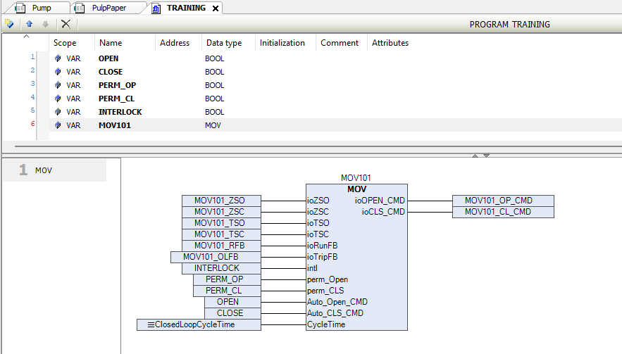
Logic Block Illustration
The MOV logic block provides a structured interface for automating and monitoring a motor-operated valve within a PLC-based control system. This block handles the execution of control commands, feedback processing, alarm generation, and interlock checks.
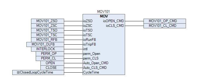
A visual representation of the MOV block showing its place in the logic and I/O system.
In the above picture, we are showing that how to use the MOV_Inching block.
Pins Information
| Signal | Type | Description |
|---|---|---|
ioZSO |
BIT | Valve Open Feedback – Indicates valve is fully open. |
ioZSC |
BIT | Valve Close Feedback – Indicates valve is fully closed. |
ioTSO |
BIT | Torque Open Feedback – Torque switch signal when valve opens. |
ioTSC |
BIT | Torque Close Feedback – Torque switch signal when valve closes. |
ioRunFB |
BIT | Feedback indicating the motor is running. |
ioTripFB |
BIT | Indicates motor tripped (protection relay). |
HMI_Open_CMD |
BIT | Valve Open command from HMI. |
HMI_CLS_CMD |
BIT | Valve Close command from HMI. |
Auto_Open_CMD |
BIT | Valve Open command from other logic blocks (Auto mode). |
Auto_CLS_CMD |
BIT | Valve Close command from other logic blocks (Auto mode). |
Mode |
BIT | Manual = 0, Auto = 1. |
ioOPEN_CMD |
BIT | Output signal to open the valve. |
ioCLS_CMD |
BIT | Output signal to close the valve. |
perm_Open |
BIT | External permissive for Open command. Must be TRUE to allow motion. |
perm_CLS |
REAL | External permissive for Close command. |
intl |
BIT | External interlock. TRUE means interlock is active and motion is blocked. |
FB_Fault |
BIT | ZSO/ZSC not received within configured time. |
CMD_Fault |
BIT | Run feedback not received after command OR feedback received without command. |
unrecog_operation |
BIT | Valve is running without valid open/close feedback, e.g., inconsistent state. |
Run_FB_Timer |
REAL | Configured time to wait for motor run feedback after issuing command. |
Run_FB_Counter |
REAL | Runtime counter while waiting for motor run feedback. |
ZS_Timer |
BIT | Activates during valve travel from ZSO → ZSC or ZSC → ZSO. |
ZS_Counter |
REAL | Runtime duration of valve movement. |
opened_time |
REAL | Time duration the valve has been open. |
closed_time |
REAL | Time duration the valve has been closed. |
open_count |
DINT | Number of valve open operations (count). |
close_count |
DINT | Number of valve close operations (count). |
R_Trig_ZSO |
R_TRIG | Rising edge trigger for Open feedback. |
R_Trig_ZSC |
R_TRIG | Rising edge trigger for Close feedback. |
valve_running |
BIT | Internal signal indicating valve is in motion. |
HMI_Interface_hardware |
WORD | Hardware interface data exchanged with HMI. |
CycleTime |
REAL | Main program cycle time of logic block. |
Desc |
STRING(10) | Tag name of the MOV block (max. 10 chars). |
TagName |
STRING(12) | Description of the MOV block (max. 12 chars). |
Operational Summary
- The logic block operates in Manual (HMI control) or Auto (external logic) mode.
- Only one command is executed at a time (either open or close).
- Safety interlocks and permissives are evaluated before any valve motion.
- If feedback is missing or inconsistent, fault flags are raised.
- Motion duration and state transitions are monitored using ZS_Timers and Run Feedback Timers.
- Usage analytics (open/close count and duration) are tracked for diagnostics and maintenance.
Training Demo Video
Demonstration video is available , How to use the Daca Logic Block through Library:
MOV-ON/OFF Block Demo - TPW Logic Setup
Best Practices
- Always validate PERM_OPEN, PERM_CLOSE, and INTERLOCK before allowing valve movement.
- For safety, faulted valves (TRIP state) must be reset manually using the faceplate Reset button or
RESETpin. - Keep
RUN_FB_TIMEOUTandZS_FB_TIMEOUTparameters conservative to avoid false positives in slow-acting valves.
Tip:
This logic ensures synchronized operation between field signals and faceplate visualizations, enabling safe and operator-friendly MOV control.