Motor Block Documentation
- Type: BI-directional Motor
- Direction: Forward and Reverse
- Control Modes: Auto / Manual
- Application: Ideal for applications requiring coordinated movement in two dimensions, such as CNC machining, 2D plotting, laser engraving, and pick-and-place operations.
Block Icon
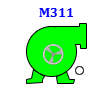
- 1 Tag Number: Displays the process tag.
- 2 Motor body: Displays information regarding the motor’s status and operation.
- 3 Moving Ring : Displays the direction of the motor(reverse or forward).
Motor REV Block Icon – Status Indicators
The motor REV block icon provides a visual representation of the motor’s state using color-coded indicators. Each color or blinking combination signifies a specific operating condition, helping operators quickly identify the motor's current status.
- On Clicking the block icon the faceplate will open.
i. Red : Motor is ready to run.

ii. Green : Motor is running.
iii. Blinking Magenta and Red : Motor is Tripped.

iv. Blinking Yellow and Red : Permission not satisfied in Motor .

v. Blinking Blue and Red : Interlock occured in Motor .

vi. Green with yellow circle : Motor running with permission bypassed .

vii. Green with yellow Blue : Motor running with interlock bypassed .

Motor Faceplate
In the Motor REV faceplate, there are 4 tabs:
-
Operation Tab : For the operation of the motor.
-
Basic Tab : Displays basic feedback and operational summary.
-
Advance Tab : Advanced options for motor configuration and setup.
-
Diagnostics Tab : Shows all feedback and diagnostic parameters.
Operator Tab Description
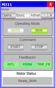
Operating Mode:
- AUTO – Enables automatic mode (commands from logic or PLC).
- MAN – Enables manual mode (commands via HMI).
- The currently selected mode is highlighted in green.
Control Command:
- START FWD(forward) – Sends command to start the motor in Clockwise direction which can be seen in block icon.
- START REV(reverse) – Sends command to start the motor in anticlockwsie direction which can be seen in block icon.
- STOP – Sends command to stop the motor.
- These buttons are only active in manual mode.
Feedbacks:
| Feedback | Description | Status Indicator |
|---|---|---|
| INTL | Interlock conditions are valid | 🟢 = OK 🟡 = Interlock Occurred |
| PERM FWD | Start motor in clockwise permission | 🟢 = OK 🟡 = Permission Not Satisfied |
| PERM REV | Start motor in anticlock permission | 🟢 = OK 🟡 = Permission Not Satisfied |
| Trip Feedback | Indicates motor fault or trip condition. | = TRIP OK = TRIP |
Motor Status:
- This field displays the current state of the motor.
- Status example in image:
Ready_MAN
> Meaning: Motor is ready and in manual mode.
Basic Tab Description
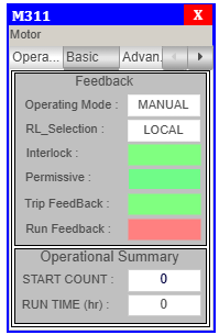
Feedbacks:
| Label | Description | Example Shown |
|---|---|---|
| Operating Mode | Displays the current control mode of the motor. | MANUAL OR AUTO |
| RL_Selection | Shows the remote/local control selection. | LOCAL OR REMOTE |
| Interlock | Indicates whether all interlocks are satisfied. | 🟢 = OK 🟡 = Interlock Occurred |
| Permissive FWD | Shows if permissive conditions are met for motor start in clockwise direction. | 🟢 = OK 🟡 = Permission Not Satisfied |
| Permissive REV | Shows if permissive conditions are met for motor start in anticlockwise direction. | 🟢 = OK 🟡 = Permission Not Satisfied |
| Trip Feedback | Indicates motor fault or trip condition. | = TRIP OK = TRIP |
| Run FB FWD | Shows whether the motor is currently running in clockwise direction. | 🟢 = Running 🔴 = Not Running |
| Run FB REV | Shows whether the motor is currently running in anticlockwise direction. | 🟢 = Running 🔴 = Not Running |
Operational Summary:
- RUN TIME – Total Motor Run time.
Advance Tab Description
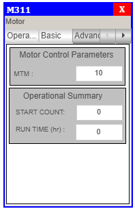
Operational Summary:
- RUN TIME – Total Motor Run time.
Motor REV Diagnotics Tab
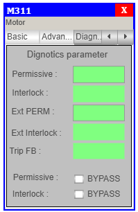
Diagnotics parameter
- Permissive FWD –
greencolor when permission FWD is OK andyellowcolor when permission FWD not satisfy. - Permissive REV –
greencolor when permission REV is OK andyellowcolor when permission REV not satisfy. - Interlock –
greencolor when Interlock is OK andyellowcolor when Interlock occurs. - Trip –
greencolor when Trip is OK andmagentacolor when Trip occurs. - Perm FWD – click on checkbox to
bypassthe permission for clockwise direction. - Perm REV – click on checkbox to
bypassthe permission for anticlockwise direction. - Interlock – click on checkbox to
bypassthe interlock.