Power Supply Connection to FTA
Introduction
Field Terminal Assemblies (FTAs) act as the interface between your I/O modules and field devices. While Passive FTAs require no power, Active FTAs must be connected to a 24V DC supply to power their internal diagnostics and electronics. Proper installation of this power connection is crucial for safe and reliable operation.
Applicable for:
- ✅ Active FTAs (Analog Output, Digital Input)
- ❌ Not applicable for Passive FTAs
Step 1: Turn Off Power Only for the FTA You Are Installing
- Do not switch off the entire Switched-Mode Power Supply (SMPS) or system power, as it may shut down the whole plant.
- Find the fuse terminal block connected to the FTA module you want to install.
- Open or disconnect only that fuse to cut power to just that FTA.
- Once the power to that FTA is off, you can safely begin the installation.
Step 2: Locate Power Terminals on the FTA
- Find the designated +24V and 0V screw terminals on your FTA.
-
These terminals are generally marked clearly on the FTA label or housing.
-
🔴 +24V Terminal – Connects to the positive lead of the power supply
- ⚫ 0V Terminal – Connects to the negative/ground lead
📌 Always refer to the product’s datasheet to verify terminal positions and specifications.
Step 3: Prepare the Wires
- Use wire sizes between 0.2 mm² and 2.5 mm² depending on your FTA specs.
- Strip approximately 7 mm of insulation from the wire ends.
- Crimp ferrules (recommended) to prevent wire fraying and ensure better conductivity.
Step 4: Connect the Wires to the FTA
- Insert the red wire into the +24V terminal
- Insert the black or blue wire into the 0V terminal
- Tighten the terminal screws to 0.5–0.6 Nm torque using a screwdriver.
⚠️ Ensure wires are securely fastened with no exposed copper strands.
Step 5: Final Verification
- Recheck that all terminal screws are tight and no strands are loose.
- Make sure the polarity is correct: +24V to red, 0V to black/blue.
Step 6: Power ON and Check Status
- Turn ON the 24V DC power supply
- Check the Power LED on the FTA — it should light up green, indicating proper operation.
- If the LED does not turn on, recheck wiring and supply voltage.
Connection of Prefabricated Cables (I/O Module ➜ FTA)
Introduction
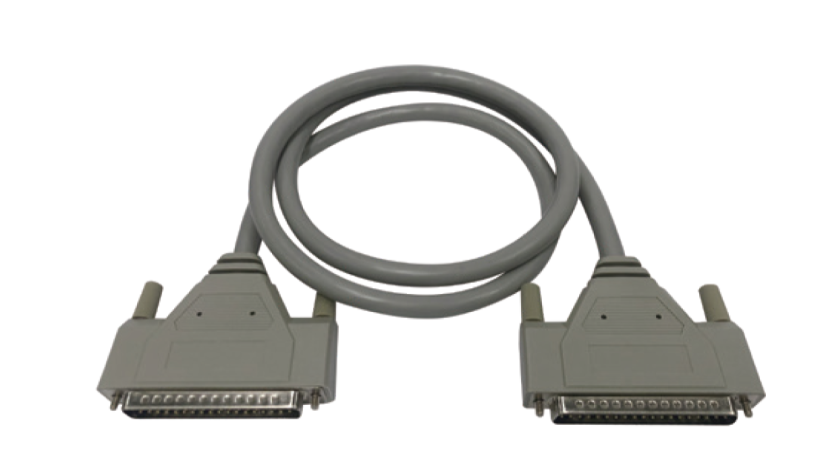
Prefabricated cables provide a quick and error-free method of connecting Saksham I/O modules to FTAs using D-Sub connectors. These cables minimize manual wiring errors and speed up installation with plug-and-play convenience.
Step 1: Ensure Power is OFF
- As with all wiring procedures, turn OFF the 24V DC power supply before installation to prevent short circuits or electric shock.
Step 2: Identify the Cable Ends
- Each prefabricated cable comes with 37-pin D-Sub connectors on both ends (male type).
- Use the labels or markings on the cable to determine the correct end for:
- The I/O Module
- The FTA
Step 3: Connect to the I/O Module
- Locate the D-Sub 37-pin port on your I/O module (AI, AO, DI, or DO).
- Align the connector carefully with the port.
- Gently push in and fasten the connector using UNC 4-40 screws.
🔧 Avoid over-tightening the screws as this can damage the port threading.
Step 4: Connect to the FTA
- Plug the other end of the cable into the FTA’s D-Sub 37-pin port.
- Tighten both side screws to ensure a firm and vibration-proof connection.
Step 5: Check Cable Routing
Make sure the cable is:
- Not stretched, twisted, or bent sharply
- Properly routed using DIN rail cable holders or clips
- Avoid routing cables near high-voltage lines or noisy electrical sources.
Step 6: Final Check
Confirm both ends are: - Fully inserted and secured - Free from tension or mechanical strain - Ensure no loose connections are present.
Step 7: Power ON and Test
- Turn on the 24V DC power
- Check the LED indicators on both the I/O module and the FTA
- Perform a basic I/O signal test to verify proper communication between module and FTA
📌 Important Notes:
- Label each cable at both ends for easy identification during maintenance.
- Use dust covers on unused D-Sub ports to protect from contaminants.