Visualization Documentation – PID Block
Usage of PID Block through SCADA Template
The PID block provides Proportional–Integral–Derivative control for closed-loop automation systems.
It is used to regulate process variables (temperature, pressure, flow, etc.) by manipulating an output to maintain a desired setpoint.
Within the TPW SCADA template system, the PID block is available as a template-based graphical icon in the Visu_page.
This reusable component can be inserted into any visualization screen and linked to its corresponding logic instance for seamless process control integration.
Integrating the PID Block into Visualization steps are given below:
1. Open the Visualization Page
- Launch your CODESYS project.
- Navigate to the visualization screen where you want to add PID control (e.g.,
PID_Control,Main_HMI, etc.).
2. Insert the PID Block Icon from Scada_test Visu Page
- Open the Visualization Toolbox Go to Current Project.
- Drag or drop the PID Block icon to your Visualization page.
- Or Just Copy the PID Block Icon from the
Scada_testvisu page and Paste into your Visualization page.
✅ This promotes visual consistency and supports template-based reuse.
3. Link the PID Block to Its Logic Instance
Follow these steps to bind the block icon to your logic:
- Select the PID block icon.
- click on the block icon Properties tab open automatically → Properties.
- Go to the References and Expand the references.
- you will see bl_PID Expand that also.
- set the path in front of the tagPID by Double clicking on empty space and select the required tag.
- Build and run the project.
- During runtime, verify that live values like
PV,SVandMVfunctioning.
PID Block Icon – Visualization Behavior
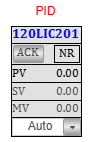
Basic follwing activities can be done from the block icon- - Mode switching (Auto/Manual) - Setpoint changes - Live process monitoring
Clicking the Tagname or graphic of the PID block icon opens a faceplate:
PID Faceplate Overview
The faceplate is divided into two user-level tabs:
- Basic Tab – For operators
- Advanced Tab – For engineers or service personnel
Faceplate - Basic Tab
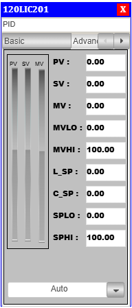
Allows basic control interactions, such as setting SP and monitoring PV/MV.
Visible to all users, including operators.
PID Parameters Details - Basic Tab
| Section | Parameter | Description |
|---|---|---|
| Process Values | PV |
Live value of the measured process variable. |
SV |
Setpoint – target value for process control. | |
MV |
Controller output sent to actuator. | |
| Output Limits | MVLO |
Minimum limit for manipulated value. |
MVHI |
Maximum limit for manipulated value. | |
| Setpoint Control | L_SP |
Lower engineering range limit for setpoint. |
C_SP |
Default or central setpoint. | |
SPLO |
Setpoint runtime low override limit. | |
SPHI |
Setpoint runtime high override limit. | |
| PV Bar | PV |
On the left side there is PV bar which show the PV value in visual form. |
| SV Bar | SV |
On the left side there is PV bar which show the SV value in visual form. |
| MV Bar | MV |
On the left side there is PV bar which show the MV value in visual form. |
| Mode Selector | Mode |
Select the mode of the PID By clicking on the dropdown arrow. |
Operators can adjust the SP if access permissions allow.
MV is automatically calculated based on control action.
Faceplate - Advanced Tab
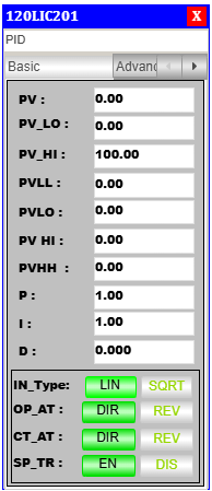
Offers engineering-level access for tuning and alarms.
Access to this tab is typically restricted via role-based login.
PID Parameters Details - Advance Tab
| Section | Parameter | Description |
|---|---|---|
| Process Values | PV |
Live value of the measured process variable. |
| Process Values Limit | PV_LO |
Lower limit for the processs value. |
PV_HI |
Higher limit for the processs value. | |
| Alarming Limits | PVLL |
Very low (critical) alarm. |
PVLO |
Low warning limit for PV. | |
PVHI |
High warning limit for PV. | |
PVHH |
Very high (critical) alarm. | |
| Tuning Parameters | P |
Proportional gain. |
I |
Integral time – used to eliminate steady-state error. | |
D |
Derivative time – used to anticipate error changes. | |
| Controller Config | IN_Type |
Input type: Linear (LIN) or Square Root (SQRT). |
OP_AT |
Output action: Direct (DIR) or Reverse (REV). |
|
CT_AT |
Control action for logic: Direct (DIR) or Reverse (REV). |
|
| Setpoint Behavior | SP_TR |
Setpoint tracking mode enable/disable. |
Adjust these settings during commissioning or maintenance under supervision.
Incorrect tuning may result in unstable control behavior.
Integration Notes
- Always declare the PID logic block (
fb_PID) in your program before linking in visualization. - Use access roles to restrict the Advanced tab.
- You can enhance the block by integrating alarm banners or event logs via SCADA features.
- Apply visibility conditions to reflect block enable/fault status.
Demo or Training Video
🎥 Watch Demo – TPW PID Block Visualization Walkthrough
This video demonstrates inserting, linking, and tuning the PID block within the TPW SCADA template.
Summary
The PID block enables precise control of process variables in a graphical and user-friendly environment.
Through its template-based integration in TPW’s HMI, it offers:
✅ Real-time monitoring and tuning
✅ Role-based access to advanced settings
✅ Drag-and-drop deployment using Visu_page
✅ Reliable interface for process stability
The PID block is ideal for operators and engineers managing continuous processes requiring accurate control.