AI FTA Wiring Diagram
Wiring Diagram – AI FTA (Analog Input Field Terminal Assembly)
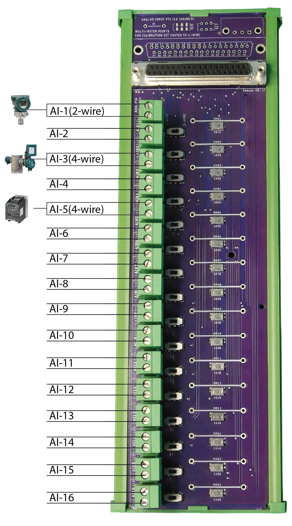
What is AI FTA?
The AI FTA is designed to simplify field wiring by allowing direct connections from analog field instruments (2-wire or 4-wire transmitters) to the analog input module.
Each channel supports individual selection between 2-wire and 4-wire modes using a switch, ensuring high flexibility and ease of use.
Wiring Sections
Analog Signal Wiring
- Each of the 16 channels can be configured as 2-wire or 4-wire input
- Channel Numbering: CH1 to CH16
- Terminal Layout: Every channel has three main terminals:
- SIG
- COM
- +24V (for 2-wire power supply)
Wire Transmitter Connection
- Set the corresponding switch for the channel to "2-wire"
Wiring:
- Connect + of transmitter to +24V terminal
- Connect – of transmitter to SIG terminal
- COM is internally connected for current return
Shield / Grounding
- Use shielded twisted pair cables for signal wires
- Connect shielding to the designated SHIELD terminal or ground bar for noise reduction
- Avoid grounding at both ends to prevent ground loops
Important Wiring Guidelines
- ✅ Ensure proper switch selection (2W/4W) before wiring
- ❌ Do not connect both 2-wire and 4-wire on the same channel
- 🧪 Use multimeter test points for diagnostics without removing connections