AO (Analog Output) Block Documentation
Overview
The AO block converts a real-valued analog signal (e.g., a PID output) into a hardware-compatible raw value to be sent to an analog output module (DAC). The output can be scaled and reversed, and alarms are triggered based on configured thresholds with hysteresis and acknowledgment logic.
This block can be used for: - Valve or actuator control - VFD output signal - Pressure or level control - Process output signal representation
AO Logic Block Illustration
The following illustration shows how the AO block is linked with the physical analog output channel. It receives inputs from logic (e.g., PID output) and sends processed, scaled, raw values to the hardware.
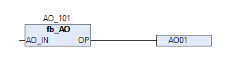
Showing the AO block with AO channel in the above picture.
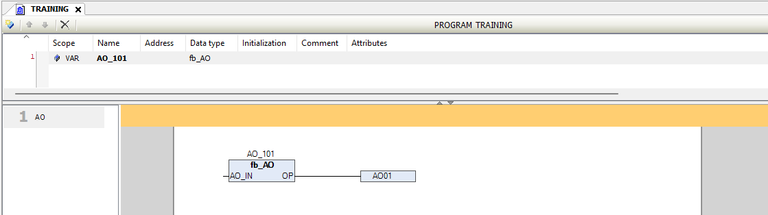
In the above picture, we are showing that how to use the AO block
Pins Information
| Signal | Type | Direction | Description |
|---|---|---|---|
AO_IN |
REAL | Input | Analog value from logic (e.g., PID block output) |
IN_LO |
REAL | Input | Minimum Input value (e.g., 0.0) |
IN_HI |
REAL | Input | Maximum Input value (e.g., 100.0) |
OP_LO |
WORD | Input | Minimum raw Output value for AO Channel |
OP_HI |
WORD | Input | Maximum raw Output value for AO Channel |
DIR |
BOOL | Input | FALSE = Direct scaling, TRUE = Reverse |
ACK |
BOOL | Input | Alarm acknowledge input |
RTN_ACK_REQD |
BOOL | Input | Return-to-normal condition requires acknowledgment if TRUE |
OPLL |
REAL | Input | Very low limit of process value |
OPLO |
REAL | Input | Low limit of process value |
OPHI |
REAL | Input | High limit of process value |
OPHH |
REAL | Input | Very high limit of process value |
HYST |
REAL | Input | Hysteresis for alarm reset |
OP |
WORD | Output | Final raw value to be written to DAC module |
OP_LL_ALM |
BOOL | Output | Alarm: TRUE if AO_IN ≤ OPLL |
OP_LO_ALM |
BOOL | Output | Alarm: TRUE if AO_IN ≤ OPLO |
OP_HI_ALM |
BOOL | Output | Alarm: TRUE if AO_IN ≥ OPHI |
OP_HH_ALM |
BOOL | Output | Alarm: TRUE if AO_IN ≥ OPHH |
Acknowledged |
BOOL | Output | Becomes TRUE after alarm is acknowledged |
Functional Description
Input Scaling Logic
The AO block linearly maps AO_IN from the engineering range [IN_LO … IN_HI] to a corresponding raw value between [OP_LO … OP_HI].
Alarm Handling
The AO block monitors AO_IN for the following alarm conditions:
| Condition | Alarm Bit |
|---|---|
AO_IN <= OPLL |
OP_LL_ALM = TRUE |
AO_IN <= OPLO |
OP_LO_ALM = TRUE |
AO_IN >= OPHI |
OP_HI_ALM = TRUE |
AO_IN >= OPHH |
OP_HH_ALM = TRUE |
Example:
If OPHH = 100.0 and HYST = 2.0, then:
- Alarm triggers when
AO_IN >= 100.0 - Alarm resets when
AO_IN < 98.0
Alarm Acknowledgment Logic
- When any alarm becomes active,
Acknowledged = FALSE - Operator must set
ACK = TRUEto acknowledge it - If
RTN_ACK_REQD = TRUE, the alarm remains latched even afterAO_INnormalizes, and must be acknowledged manually
Typical Application Example
| Parameter | Example Value | Description |
|---|---|---|
AO_IN |
62.5 | PID output value |
IN_LO |
0.0 | Minimum setpoint (engineering unit) |
IN_HI |
100.0 | Maximum setpoint (engineering unit) |
OP_LO |
800 | Raw output for 0% (e.g., 4 mA) |
OP_HI |
4000 | Raw output for 100% (e.g., 20 mA) |
DIR |
FALSE | Output action (Direct/Reverse) |
Advanced View
- Configure
IN_LO,IN_HI,OP_LO,OP_HI - Set alarm thresholds (
OPLL,OPLO, etc.) - Configure
RTN_ACK_REQDbehavior
Summary
| Feature | Description |
|---|---|
| Input to Output | Scales REAL input to WORD output using defined engineering and raw ranges |
| Direction | Selectable direct/reverse output |
| Alarm Generation | 4 levels of process alarm detection |
| Hysteresis | Reduces flickering by buffering alarm limits |
| Acknowledgment | Manual ACK with auto/manual return-to-normal control |
| Faceplate Support | Structured views for Operator, Technician, Engineer |
Best Practices
- Always scale
IN_LO/HIandOP_LO/HIbased on actual signal range. - Keep
HYSTsmall but effective (e.g., 1–5% of signal range). - Display
OPand alarm bits on HMI faceplate. - Use consistent logic for
ACKandRTN_ACK_REQDacross all analog signals.
Notes
- For current output use (4–20mA), scale
OP_LO = 800,OP_HI = 4000 - Ensure
AO_INis bounded within[IN_LO, IN_HI]to avoid incorrect scaling