MOTOR Logic Block Documentation
Overview
The MOTOR function block is used to control electric motors within an automation or process control system. It is designed to manage both manual and automatic operations, monitor motor health, and ensure safety through permissive and interlock logic.
This block is crucial for applications requiring reliable motor operation, feedback verification, start/stop control, and operational diagnostics.
Logic Block Description
The MOTOR block facilitates the following operations:
- Start/Stop Motor: Based on HMI/Auto commands and remote-local (RL) selection.
- Monitor Feedbacks: Ensures the motor is running or tripped using feedback inputs.
- Safety Checks: Includes internal and external interlock and permissive logic.
- Diagnostics: Provides outputs for failed feedback detection, local control detection, and fault alerts.
- Runtime Tracking: Tracks motor run time, number of starts, and delay management.
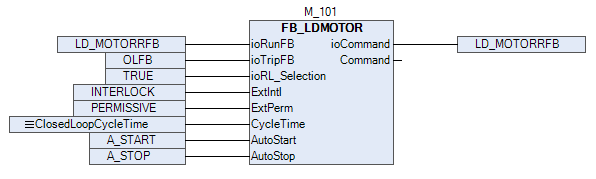
Showing the MOTOR block in the above picture.
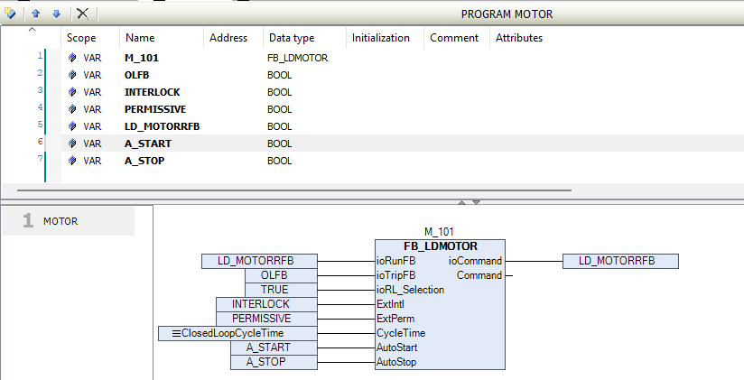
The above picture shows how the inputs and outputs are connected in the MOTOR block.
Input and Output Parameters
| Signal | Type | Description |
|---|---|---|
ioRunFB |
BIT |
Motor run feedback signal |
ioTripFB |
BIT |
Motor trip feedback signal |
ioRL_Selection |
BIT |
Remote/Local selection signal |
ioCommand |
BIT |
Motor output command |
Command |
BIT |
Motor output command from logic |
perm |
BIT |
Internal permissive condition |
intl |
BIT |
Internal interlock condition |
RFB_Fail |
BIT |
Run feedback failed (e.g., motor did not start after command) |
Diagnostics |
BIT |
General diagnostic output (e.g., motor faulted or issue detected) |
LocalStarted |
BIT |
Motor started locally |
LocalStopped |
BIT |
Motor stopped locally |
hmiStartCMD |
BIT |
HMI start command |
hmiStopCMD |
BIT |
HMI stop command |
ExtIntl |
BIT |
External interlock condition |
ExtPerm |
BIT |
External permissive condition |
AM_Sel |
BIT |
Auto/Manual selection |
AutoStart |
BIT |
Auto mode start command |
AutoStop |
BIT |
Auto mode stop command |
fp_Visible |
BIT |
Visibility of the faceplate on HMI |
RFB_CheckTime |
WORD |
Time allowed for run feedback to respond |
HMI_Interface |
WORD |
Interface code/messages for HMI display |
byPerm_Intl |
BYTE |
Combined status byte for interlock and permissive |
StartCount |
INT |
Number of motor starts |
RunTime |
REAL |
Total run time of the motor (in hours) |
MTM |
REAL |
Maximum allowed time for run feedback to appear |
RFB_FailTime |
REAL |
Time when run feedback failed |
CycleTime |
REAL |
Time for one control cycle |
IntlBypass |
BIT |
Bypass for interlock (manual override) |
PermBypass |
BIT |
Bypass for permissive (manual override) |
TagName |
STRING(10) |
Tag name for the motor (used in faceplate and diagnostics) |
Desc |
STRING(12) |
Description of the motor |
Operational Behavior
Start/Stop Sequence:
- If in Auto mode (
AM_Sel), motor will start/stop based onAutoStart/AutoStop. - If in Local mode and
RL_Selection = FALSE, motor will start onhmiStartCMD.
Safety Conditions:
- The motor will only start if all permissive and interlock conditions are valid, or bypass is enabled.
Feedback Monitoring:
- After issuing a start command, the block waits for a valid
ioRunFBwithinRFB_CheckTime. - If not received,
RFB_Failis set.
Diagnostics and Messaging:
- Faults, feedback issues, and local operation are logged through
DiagnosticsandHMI_Interface.
Best Practices
- Ensure accurate
RFB_CheckTimeconfiguration to match motor start delay characteristics. - Use
IntlBypassandPermBypassonly during maintenance or special cases. - Monitor
RunTimeandStartCountfor motor maintenance and analytics. - Use descriptive
TagNameandDescvalues for better HMI display and diagnostics. - Properly map
HMI_Interfaceto corresponding HMI messages for real-time troubleshooting.
Summary
The MOTOR block provides a safe, intelligent, and flexible structure to control electric motors within automation systems. It enables both manual and automatic modes, incorporates fault detection and interlock logic, and ensures that motor operations comply with system safety and reliability requirements.
Designed to enhance motor protection, simplify control logic, and streamline HMI interactions.